こんにちは(@t_kun_kamakiri)
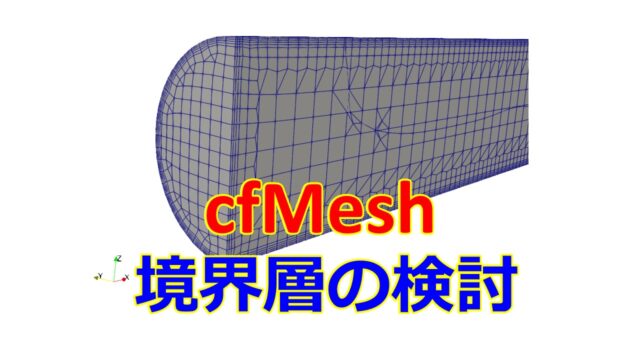
OpenFOAMで流体解析をする際のメッシャーであるsnappyHexMeshを使ったメッシュ境界層の検討した内容について自身の理解を深めるためにまとめました。
特に形状が複雑である場合にデフォルトの設定でメッシュ生成を行うと、形状変化が激しい部分でメッシュが作れていなかった、メッシュが潰れてガタガタになったりします。
その中でも特に境界層メッシュがうまく作れないという問題に直面しました。
snappyHexMeshの理解も少しずつ進んでおり、snappyHexMeshでのメッシュ再分割については前回の記事で書きました。
詳細の設定は公式サイトをご参考ください。
snappyHexMeshでの境界層設定について考えるため、本記事ではこのような形状の場合を考えます。
※形状に特に意味はありません。
後ほど面でのメッシュ再分割をしたいので、FreeCADで面に名前を付けておきました。
FreeCADを使ったモデル作成は動画を用意しましたので、再現したい方はこちらをどうぞ。
面に名前を付けた際にstlを掃き出す便利なマクロは以下の記事をご参考ください。
※動画内では本記事の面の名前の付け方と異なります。
ParaViewを起動してみましょう。
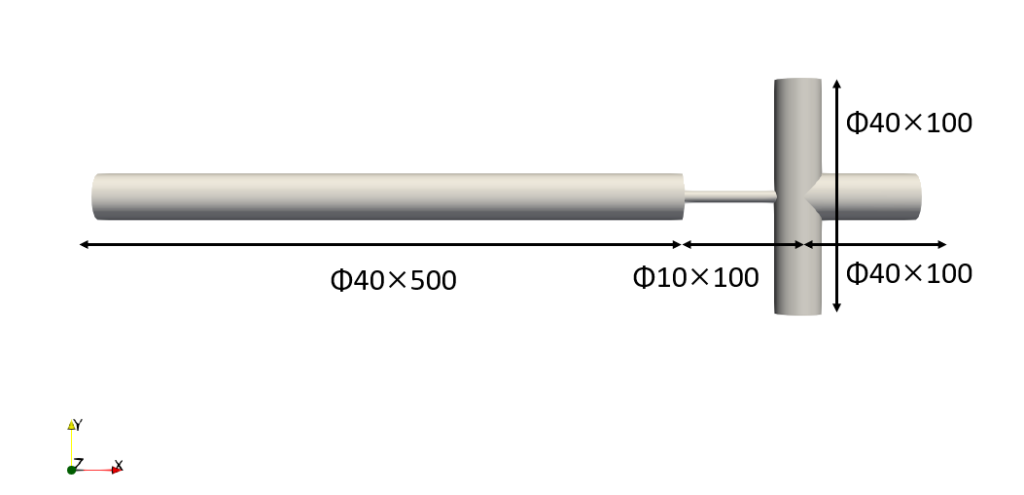
単純な形状ですが太い円柱と細い円柱など、強弱があるためメッシュ再分割と境界層をどのように入れるかが肝になりそうです。
- snappyHexMeshでの境界層メッシュの設定方法
- 境界層が上手くいかない場合の対処方法
OpenFOAM-v2012
結局cfMeshを使った方がきれいに境界層が入ったためcfMeshの利用を検討しています。
【事前準備】チュートリアルからケースファイルをコピー
snappyHexMeshを使っている適当なチュートリアルをコピーしてきます。
|
1 |
cp -r /opt/OpenFOAM/OpenFOAM-v2012/tutorials/incompressible/simpleFoam/motorBike/* . |
ファイル構成は以下のようになっています。
|
1 2 3 4 5 6 7 8 9 10 11 12 13 14 15 16 17 18 19 20 21 22 23 24 25 26 27 28 29 30 31 32 33 34 35 36 37 38 |
. ├── 0.orig │ ├── U │ ├── include │ │ ├── fixedInlet │ │ ├── frontBackUpperPatches │ │ └── initialConditions │ ├── k │ ├── nut │ ├── omega │ └── p ├── Allclean ├── Allrun ├── constant │ ├── transportProperties │ ├── triSurface │ │ └── README │ └── turbulenceProperties ├── model │ ├── model.FCStd │ ├── model.FCStd1 │ ├── model.stl │ └── model_m.stl └── system ├── blockMeshDict ├── controlDict ├── cuttingPlane ├── decomposeParDict.6 ├── ensightWrite ├── forceCoeffs ├── fvSchemes ├── fvSolution ├── meshQualityDict ├── snappyHexMeshDict ├── streamLines ├── surfaceFeatureExtractDict ├── topoSetDict └── wallBoundedStreamLines |
FreeCADで作成したモデルは数字だけしか意味を持たないため、解析で使用するの単位系がSI単位系(m-kg-sec)ならば、m(メートル)寸法になってしまいます。
これをmm(ミリメートル)に変換するために以下のコマンドを実行します。
|
1 2 3 |
cd model surfaceConvert -scale 0.001 model.stl model_m.stl cd .. |
このようにするとmodel_m.stlファイルがmm(ミリメートル)単位で扱われます。
以後、model_m.stlを使って行きます。
そして、model_m.stlをconstantフォルダにtriSurfaceがあるのでそちらにコピーします。
|
1 |
cp -r model/model_m.stl constant/triSurface/ |
特徴線を抽出します。
|
1 |
surfaceFeatureExtract |
特徴線をParaViewで確認したい場合はobj形式に変換することで読み込みが可能となります。
|
1 |
surfaceFeatureConvert constant/triSurface/model_m.eMesh constant/triSurface/model_m.obj |
ベースメッシュ作成
snappyHexMeshはベースとなるメッシュを事前に生成しておく必要があります。OpenFOAMではblockMeshでベースメッシュ生成することが多く、system/blockMeshDict内に設定を書きます。
|
1 2 3 4 5 6 7 8 9 10 11 12 13 14 15 16 17 18 19 20 21 22 23 24 25 26 27 28 29 30 31 32 33 34 35 36 37 38 39 40 41 42 43 44 45 46 47 48 49 50 51 52 53 54 55 56 |
/*--------------------------------*- C++ -*----------------------------------*\ | ========= | | | \\ / F ield | OpenFOAM: The Open Source CFD Toolbox | | \\ / O peration | Version: v2012 | | \\ / A nd | Website: www.openfoam.com | | \\/ M anipulation | | \*---------------------------------------------------------------------------*/ FoamFile { version 2.0; format ascii; class dictionary; object blockMeshDict; } // * * * * * * * * * * * * * * * * * * * * * * * * * * * * * * * * * * * * * // scale 0.001; xmax 705; xmin -10; ymax 110; ymin -110; zmax 30; zmin -30; celSize 2.5; xcelln #calc "(($xmax)-($xmin))/$celSize"; ycelln #calc "(($ymax)-($ymin))/$celSize"; zcelln #calc "(($zmax)-($zmin))/$celSize"; vertices ( ($xmin $ymin $zmin) ($xmax $ymin $zmin) ($xmax $ymax $zmin) ($xmin $ymax $zmin) ($xmin $ymin $zmax) ($xmax $ymin $zmax) ($xmax $ymax $zmax) ($xmin $ymax $zmax) ); blocks ( hex (0 1 2 3 4 5 6 7) ($xcelln $ycelln $zcelln) simpleGrading (1 1 1) ); edges ( ); boundary ( ); // ************************************************************************* // |
以下のコマンドでベースメッシュを作ります。
|
1 |
blockMesh |
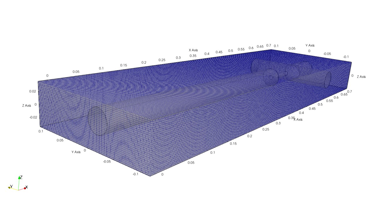
できたメッシュをParaViewで確認するとメッシュのサイズ感を確認できます。
今回はセルサイズが2.5mmとなるようにしています。
Case1:snappyHexMeshの設定
コピーしてきたチュートリアルから今回のモデルでも対応してメッシュ生成できるように修正しました。
|
1 2 3 4 5 6 7 8 9 10 11 12 13 14 15 16 17 18 19 20 21 22 23 24 25 26 27 28 29 30 31 32 33 34 35 36 37 38 39 40 41 42 43 44 45 46 47 48 49 50 51 52 53 54 55 56 57 58 59 60 61 62 63 64 65 66 67 68 69 70 71 72 73 74 75 76 77 78 79 80 81 82 83 84 85 86 87 88 89 90 91 92 93 94 95 96 97 98 99 100 101 102 103 104 105 106 107 108 109 110 111 112 113 114 115 116 117 118 119 120 121 122 123 124 125 126 127 128 129 130 131 132 133 134 135 136 137 138 139 140 141 142 143 144 145 146 147 148 149 150 151 152 153 154 155 156 157 158 159 160 161 162 163 164 165 166 167 168 169 170 171 172 173 174 175 176 177 178 179 180 181 182 183 184 185 186 187 188 189 190 191 192 193 194 195 196 197 198 199 200 201 202 203 204 205 206 207 208 209 210 211 212 213 214 215 216 217 218 219 220 221 222 223 224 225 226 227 228 229 230 231 232 233 234 235 236 237 238 239 240 241 242 243 244 245 246 247 248 249 250 251 252 253 254 255 256 257 258 259 260 261 262 263 264 265 266 267 268 269 270 271 272 273 274 275 276 277 278 279 280 281 282 283 284 285 286 287 288 289 290 291 292 293 294 295 296 297 298 299 300 301 302 303 304 305 306 307 308 309 310 311 312 313 314 315 316 317 318 319 320 321 322 323 324 325 326 327 328 329 330 331 332 333 334 335 336 337 338 339 340 341 342 343 344 345 346 347 348 349 350 351 352 353 354 355 356 357 358 359 360 361 362 363 364 365 366 367 368 369 370 371 372 373 374 375 376 377 378 379 380 381 382 383 384 385 386 387 388 389 390 391 392 393 394 395 396 397 398 399 400 401 402 403 404 405 406 407 408 409 410 411 412 413 414 415 416 417 418 419 420 421 422 423 424 425 426 427 428 429 430 431 432 433 434 435 436 437 438 439 440 |
/*--------------------------------*- C++ -*----------------------------------*\ | ========= | | | \\ / F ield | OpenFOAM: The Open Source CFD Toolbox | | \\ / O peration | Version: v2012 | | \\ / A nd | Website: www.openfoam.com | | \\/ M anipulation | | \*---------------------------------------------------------------------------*/ FoamFile { version 2.0; format ascii; class dictionary; object snappyHexMeshDict; } // * * * * * * * * * * * * * * * * * * * * * * * * * * * * * * * * * * * * * // // Which of the steps to run castellatedMesh true; snap true; addLayers true; // Geometry. Definition of all surfaces. All surfaces are of class // searchableSurface. // Surfaces are used // - to specify refinement for any mesh cell intersecting it // - to specify refinement for any mesh cell inside/outside/near // - to 'snap' the mesh boundary to the surface geometry { model_m.stl { type triSurfaceMesh; name model_m; regions { sideWall3 // Named region in the STL file { name sideWall3; // User-defined patch name } // otherwise given sphere.stl_secondSolid wallOutlet1 { name wallOutlet1; } outletXmax { name outletXmax; } outletYmax { name outletYmax; } outletYmin { name outletYmin; } sideWall2 { name sideWall2; } wall1 { name wall1; } sideWall1 { name sideWall1; } inlet { name inlet; } } } // refinementBox // { // type box; // min (-1.0 -0.7 0.0); // max ( 8.0 0.7 2.5); // } } // Settings for the castellatedMesh generation. castellatedMeshControls { // Refinement parameters // ~~~~~~~~~~~~~~~~~~~~~ // If local number of cells is >= maxLocalCells on any processor // switches from from refinement followed by balancing // (current method) to (weighted) balancing before refinement. maxLocalCells 100000000; // Overall cell limit (approximately). Refinement will stop immediately // upon reaching this number so a refinement level might not complete. // Note that this is the number of cells before removing the part which // is not 'visible' from the keepPoint. The final number of cells might // actually be a lot less. maxGlobalCells 100000000; // The surface refinement loop might spend lots of iterations refining just a // few cells. This setting will cause refinement to stop if <= minimumRefine // are selected for refinement. Note: it will at least do one iteration // (unless the number of cells to refine is 0) minRefinementCells 10; // Allow a certain level of imbalance during refining // (since balancing is quite expensive) // Expressed as fraction of perfect balance (= overall number of cells / // nProcs). 0=balance always. maxLoadUnbalance 0.10; // Number of buffer layers between different levels. // 1 means normal 2:1 refinement restriction, larger means slower // refinement. nCellsBetweenLevels 3; // Explicit feature edge refinement // ~~~~~~~~~~~~~~~~~~~~~~~~~~~~~~~~ // Specifies a level for any cell intersected by its edges. // This is a featureEdgeMesh, read from constant/triSurface for now. features ( { file "model_m.eMesh"; level 0; } ); // Surface based refinement // ~~~~~~~~~~~~~~~~~~~~~~~~ // Specifies two levels for every surface. The first is the minimum level, // every cell intersecting a surface gets refined up to the minimum level. // The second level is the maximum level. Cells that 'see' multiple // intersections where the intersections make an // angle > resolveFeatureAngle get refined up to the maximum level. refinementSurfaces { model_m { level (0 0); regions { inlet { // Surface-wise min and max refinement level level (0 0); // Optional specification of patch type (default is wall). No // constraint types (cyclic, symmetry) etc. are allowed. patchInfo { type patch; // inGroups (motorBikeGroup); } } wall1 { level (0 0); patchInfo { type wall; } } sideWall1 { level (0 0); patchInfo { type wall; } } sideWall2 { level (0 0); patchInfo { type wall; } } sideWall3 { level (0 0); patchInfo { type wall; } } wallOutlet1 { level (0 0); patchInfo { type wall; } } outletXmax { level (0 0); patchInfo { type patch; } } outletYmax { level (0 0); patchInfo { type patch; } } outletYmin { level (0 0); patchInfo { type patch; } } } } } // Resolve sharp angles resolveFeatureAngle 30; // Region-wise refinement // ~~~~~~~~~~~~~~~~~~~~~~ // Specifies refinement level for cells in relation to a surface. One of // three modes // - distance. 'levels' specifies per distance to the surface the // wanted refinement level. The distances need to be specified in // descending order. // - inside. 'levels' is only one entry and only the level is used. All // cells inside the surface get refined up to the level. The surface // needs to be closed for this to be possible. // - outside. Same but cells outside. refinementRegions { // refinementBox // { // mode inside; // levels ((1E15 4)); // } } // Mesh selection // ~~~~~~~~~~~~~~ // After refinement patches get added for all refinementSurfaces and // all cells intersecting the surfaces get put into these patches. The // section reachable from the locationInMesh is kept. // NOTE: This point should never be on a face, always inside a cell, even // after refinement. locationInMesh (0.1 0 0); // Whether any faceZones (as specified in the refinementSurfaces) // are only on the boundary of corresponding cellZones or also allow // free-standing zone faces. Not used if there are no faceZones. allowFreeStandingZoneFaces true; } // Settings for the snapping. snapControls { //- Number of patch smoothing iterations before finding correspondence // to surface nSmoothPatch 3; //- Relative distance for points to be attracted by surface feature point // or edge. True distance is this factor times local // maximum edge length. tolerance 2.0; //- Number of mesh displacement relaxation iterations. nSolveIter 30; //- Maximum number of snapping relaxation iterations. Should stop // before upon reaching a correct mesh. nRelaxIter 5; // Feature snapping //- Number of feature edge snapping iterations. // Leave out altogether to disable. nFeatureSnapIter 10; //- Detect (geometric only) features by sampling the surface // (default=false). implicitFeatureSnap false; //- Use castellatedMeshControls::features (default = true) explicitFeatureSnap true; //- Detect points on multiple surfaces (only for explicitFeatureSnap) multiRegionFeatureSnap false; } // Settings for the layer addition. addLayersControls { // Are the thickness parameters below relative to the undistorted // size of the refined cell outside layer (true) or absolute sizes (false). relativeSizes true; // Per final patch (so not geometry!) the layer information layers { //"(lowerWall|motorBike).*" inlet { nSurfaceLayers 3; } sideWall1 { nSurfaceLayers 3; } sideWall2 { nSurfaceLayers 3; } wall1 { nSurfaceLayers 3; } } // Expansion factor for layer mesh expansionRatio 1.0; // Wanted thickness of final added cell layer. If multiple layers // is the thickness of the layer furthest away from the wall. // Relative to undistorted size of cell outside layer. // See relativeSizes parameter. finalLayerThickness 0.3; // Minimum thickness of cell layer. If for any reason layer // cannot be above minThickness do not add layer. // Relative to undistorted size of cell outside layer. minThickness 0.1; // If points get not extruded do nGrow layers of connected faces that are // also not grown. This helps convergence of the layer addition process // close to features. // Note: changed(corrected) w.r.t 1.7.x! (didn't do anything in 1.7.x) nGrow 0; // Advanced settings // When not to extrude surface. 0 is flat surface, 90 is when two faces // are perpendicular featureAngle 60; // At non-patched sides allow mesh to slip if extrusion direction makes // angle larger than slipFeatureAngle. slipFeatureAngle 30; // Maximum number of snapping relaxation iterations. Should stop // before upon reaching a correct mesh. nRelaxIter 3; // Number of smoothing iterations of surface normals nSmoothSurfaceNormals 1; // Number of smoothing iterations of interior mesh movement direction nSmoothNormals 3; // Smooth layer thickness over surface patches nSmoothThickness 10; // Stop layer growth on highly warped cells maxFaceThicknessRatio 0.5; // Reduce layer growth where ratio thickness to medial // distance is large maxThicknessToMedialRatio 0.3; // Angle used to pick up medial axis points // Note: changed(corrected) w.r.t 1.7.x! 90 degrees corresponds to 130 // in 1.7.x. minMedialAxisAngle 90; // Create buffer region for new layer terminations nBufferCellsNoExtrude 0; // Overall max number of layer addition iterations. The mesher will exit // if it reaches this number of iterations; possibly with an illegal // mesh. nLayerIter 50; } // Generic mesh quality settings. At any undoable phase these determine // where to undo. meshQualityControls { #include "meshQualityDict" // Advanced //- Number of error distribution iterations nSmoothScale 4; //- Amount to scale back displacement at error points errorReduction 0.75; } // Advanced // Write flags writeFlags ( scalarLevels layerSets layerFields // write volScalarField for layer coverage ); // Merge tolerance. Is fraction of overall bounding box of initial mesh. // Note: the write tolerance needs to be higher than this. mergeTolerance 1e-6; // ************************************************************************* // |
長いですが基本的な構成は以下のようになっています。
|
1 2 3 4 5 6 7 8 9 10 11 12 13 14 15 16 17 18 19 20 21 22 23 24 25 26 27 28 29 30 31 32 33 34 35 36 37 38 39 40 41 42 43 44 45 46 47 48 49 50 51 52 53 54 55 56 57 58 59 60 61 62 63 64 65 |
castellatedMesh true; snap true; addLayers true; geometry{ model_m.stl { regions { } } } castellatedMeshControls { features ( { } ); refinementSurfaces { } maxLocalCells 100000000; maxGlobalCells 100000000; minRefinementCells 10; maxLoadUnbalance 0.10; nCellsBetweenLevels 3; resolveFeatureAngle 30; locationInMesh (0.1 0 0); allowFreeStandingZoneFaces true; } snapControls { nSmoothPatch 3; tolerance 2.0; nSolveIter 30; nRelaxIter 5; nFeatureSnapIter 10; implicitFeatureSnap false; explicitFeatureSnap true; multiRegionFeatureSnap false; } addLayersControls { layers { } relativeSizes true; expansionRatio 1.0; finalLayerThickness 0.3; minThickness 0.1; nGrow 0; featureAngle 60; slipFeatureAngle 30; nRelaxIter 3; nSmoothSurfaceNormals 1; nSmoothNormals 3; nSmoothThickness 10; maxFaceThicknessRatio 0.5; maxThicknessToMedialRatio 0.3; minMedialAxisAngle 90; nBufferCellsNoExtrude 0; nLayerIter 50; } |
以下のコマンドでメッシュ生成を行います。
|
1 |
snappyHexMesh |
メッシュは2.5mmなのでΦ10の径に対してはギリギリ4点のセルが入れることができます。形状としてはガタガタです。
snappyHexMeshには指定した面のメッシュを再分割することができるため、後ほど修正します。それよりも、Φ40×500の太い円柱の端で境界層が上手く入っていないことの方が気になりますね。
Case2:境界層のサイズを指定する
addLayersControlsが境界層を設定する部分です。
relativeSizesはtureにしているとベースメッシュの大きさに対する割合となり、falseならminThicknessとfinalLayerThicknessの値は境界層の厚みの絶対値となります。
relativeSizesはtureにしているため、ベースメッシュの変化が大きい場合は境界層の割合によってメッシュサイズが変わってしまうため、上手くつなぐことができずにいるのかなと思います。
以下のように変えてみるとどうでしょうか。
- relativeSizes false;
- finalLayerThickness 0.001;
- minThickness 0.001;
|
1 2 3 4 5 6 7 8 9 10 11 12 13 14 15 16 17 18 19 20 21 22 |
addLayersControls { layers { } relativeSizes false; expansionRatio 1.0; finalLayerThickness 0.001; minThickness 0.001; nGrow 0; featureAngle 60; slipFeatureAngle 30; nRelaxIter 3; nSmoothSurfaceNormals 1; nSmoothNormals 3; nSmoothThickness 10; maxFaceThicknessRatio 0.5; maxThicknessToMedialRatio 0.3; minMedialAxisAngle 90; nBufferCellsNoExtrude 0; nLayerIter 50; } |
Φ40の端での境界層は相変わらず潰れています。
relativeSizesはfalseでの境界層の厚みの絶対値を指定する方法は思わぬところで失敗する可能性を含みます。
例えば、今回のような細い円柱の径がΦ10なので境界層の設定次第ではメッシュがうまく作れない場合があります。
- finalLayerThickness 0.0025;
- minThickness 0.0025;

全体の境界層厚みの絶対値を指定するのは形状をすべて把握している必要があります。設定忘れでメッシュが作れていなかったりと困難な場合が多いので、やはりベースメッシュの割合で境界層厚みを判断してくれる「relativeSizes true;」で進めようと思います。
Case3:featureAngleの変更
コーナー付近で境界層が崩れるのを防ぐために、境界層パラメータとしてfeatureAngleがあります。featureAngle値を大きくすることで端での境界層の崩れを防ぐことができます。
relativeSizesはtrueにしてベースメッシュに対する境界層設定の割合に戻しておきます。
-
featureAngle130;
- relativeSizestrue;
- finalLayerThickness0.3;
- minThickness0.1;
|
1 2 3 4 5 6 7 8 9 10 11 12 13 14 15 16 17 18 19 20 21 22 23 |
addLayersControls { layers { } relativeSizes true; expansionRatio 1.0; finalLayerThickness 0.3; minThickness 0.1; nGrow 0; //featureAngle 60; featureAngle 130; slipFeatureAngle 30; nRelaxIter 3; nSmoothSurfaceNormals 1; nSmoothNormals 3; nSmoothThickness 10; maxFaceThicknessRatio 0.5; maxThicknessToMedialRatio 0.3; minMedialAxisAngle 90; nBufferCellsNoExtrude 0; nLayerIter 50; } |
Case4:特徴線で再分割する
境界の端でもう少し細かいメッシュサイズになっていれば良いのかと思って、特徴線を再分割してみます。
|
1 2 3 4 5 6 7 8 9 10 11 12 13 14 |
castellatedMeshControls { features ( { file "model_m.eMesh"; level 2; } ); refinementSurfaces { } (以下省略) } |
Φ40の方はメッシュサイズが細かくなったので何となく境界層が上手くいっているようにごまかされているですが、Φ10の細い円柱では境界層が両端で潰れてしまっています。
やはり境界層とメッシュの再分割は相性が良くないのかもしれません。
Case5:Φ10の細い円柱のメッシュ再分割
特徴線を使わずにΦ10の細い円柱のメッシュ再分割レベルを1にします。
こうすることでベースのメッシュより1段階細かいメッシュになります。
|
1 2 3 4 5 6 7 8 9 10 11 12 13 14 15 16 17 18 19 20 21 22 23 24 25 26 27 28 |
castellatedMeshControls { features ( { file "model_m.eMesh"; level 0; } ); refinementSurfaces { model_m { level (0 0); regions { sideWall2 { level (1 1); patchInfo { type wall; } } } } } (以下省略) } |
Case6:境界層は円柱の側面だけにする
円柱の端と円の面で境界を作ろう無理やりメッシュを変形させるから潰れてしまうのではないかと思い、境界層は円柱の側面だけにしました。
|
1 2 3 4 5 6 7 8 9 10 11 12 13 14 15 16 17 18 19 20 21 22 23 24 25 26 27 28 29 30 31 32 33 34 35 36 37 38 39 40 41 42 43 44 45 46 47 48 49 50 51 52 53 54 55 56 57 58 59 60 |
addLayersControls { layers { //"(lowerWall|motorBike).*" inlet { nSurfaceLayers 3; } sideWall1 { nSurfaceLayers 3; } sideWall2 { nSurfaceLayers 3; } wall1 { nSurfaceLayers 3; } sideWall3 { nSurfaceLayers 3; } wallOutlet1 { nSurfaceLayers 3; } outletXmax { nSurfaceLayers 3; } outletYmax { nSurfaceLayers 3; } outletYmin { nSurfaceLayers 3; } } relativeSizes true; expansionRatio 1.0; finalLayerThickness 0.3; minThickness 0.03; nGrow 0; // featureAngle 60; featureAngle 130; slipFeatureAngle 30; nRelaxIter 3; nSmoothSurfaceNormals 1; nSmoothNormals 3; nSmoothThickness 10; maxFaceThicknessRatio 0.5; maxThicknessToMedialRatio 0.3; minMedialAxisAngle 90; nBufferCellsNoExtrude 0; nLayerIter 50; } |
きれいに表面が入っているように見えますが、Φ10の細い円柱からΦ40の2つに分かれるつなぎ目でメッシュが潰れています。特に、Φ40の円柱からΦ10の円柱へのつなぎ目の面に境界層が無いので、流体流れの再現性が悪かったり、直交性が悪いと疑似的な数値拡散が起こり良くありません。

しかも境界条件でメッシュが層にならない可能性もあります。
やはり、再分割が行われている部分では2つの境界層のつなぎ目でメッシュが潰れてしまうようです。
最終的なsnappyHexMeshの設定
境界層がうまく入らない部分がありますが、境界面の全てに境界層を入れる設定にしました。
|
1 2 3 4 5 6 7 8 9 10 11 12 13 14 15 16 17 18 19 20 21 22 23 24 25 26 27 28 29 30 31 32 33 34 35 36 37 38 39 40 41 42 43 44 45 46 47 48 49 50 51 52 53 54 55 56 57 58 59 60 61 62 63 64 65 66 67 68 69 70 71 72 73 74 75 76 77 78 79 80 81 82 83 84 85 86 87 88 89 90 91 92 93 94 95 96 97 98 99 100 101 102 103 104 105 106 107 108 109 110 111 112 113 114 115 116 117 118 119 120 121 122 123 124 125 126 127 128 129 130 131 132 133 134 135 136 137 138 139 140 141 142 143 144 145 |
/*--------------------------------*- C++ -*----------------------------------*\ | ========= | | | \\ / F ield | cfMesh: A library for mesh generation | | \\ / O peration | | | \\ / A nd | Author: Franjo Juretic | | \\/ M anipulation | E-mail: franjo.juretic@c-fields.com | \*---------------------------------------------------------------------------*/ FoamFile { version 2.0; format ascii; class dictionary; location "system"; object meshDict; } // * * * * * * * * * * * * * * * * * * * * * * * * * * * * * * * * * * * * * // surfaceFile "model_m.stl"; // minCellSize 0.001; maxCellSize 0.01; boundaryCellSize 0.01; localRefinement { "sideWall3" { cellSize 0.004; } "wallOutlet1" { cellSize 0.004; } "outletYmax" { cellSize 0.004; } "outletYmin" { cellSize 0.004; } "sideWall2" { cellSize 0.001; } "wall1" { cellSize 0.004; } "sideWall1" { cellSize 0.004; } "inlet" { cellSize 0.004; } // "orifice0[3-6].*" // { // cellSize 0.3; // } } boundaryLayers { nLayers 3; thicknessRatio 1.0; // maxFirstLayerThickness 0.001; patchBoundaryLayers { "sideWall3" { nLayers 3; thicknessRatio 1.2; maxFirstLayerThickness 0.001; allowDiscontinuity 0; } "wallOutlet1" { nLayers 3; thicknessRatio 1.2; maxFirstLayerThickness 0.001; allowDiscontinuity 0; } "outletXmax" { nLayers 3; thicknessRatio 1.2; maxFirstLayerThickness 0.001; allowDiscontinuity 0; } "outletYmax" { nLayers 3; thicknessRatio 1.2; maxFirstLayerThickness 0.001; allowDiscontinuity 0; } "outletYmin" { nLayers 3; thicknessRatio 1.2; maxFirstLayerThickness 0.001; allowDiscontinuity 0; } "sideWall2" { nLayers 3; thicknessRatio 1.2; maxFirstLayerThickness 0.001; allowDiscontinuity 0; } "wall1" { nLayers 3; thicknessRatio 1.2; maxFirstLayerThickness 0.001; allowDiscontinuity 0; } "sideWall1" { nLayers 3; thicknessRatio 1.2; maxFirstLayerThickness 0.001; allowDiscontinuity 0; } "inlet" { nLayers 3; thicknessRatio 1.2; maxFirstLayerThickness 0.001; allowDiscontinuity 0; } // "orifice.*" // { // nLayers 4; // thicknessRatio 1.2; // maxFirstLayerThickness 0.2; // allowDiscontinuity 0; // } } optimiseLayer 1; } // ************************************************************************* // |


ちなみにメッシュ品質は
|
1 |
checkMesh |
により確認ができます。
|
1 2 3 4 5 6 7 8 9 10 11 12 13 14 15 16 17 18 19 20 21 22 23 24 25 26 27 28 29 30 31 32 33 34 35 36 37 38 39 40 41 42 43 44 45 46 47 48 49 50 51 52 53 54 55 56 57 58 59 60 61 62 63 64 65 66 67 68 69 70 |
Mesh stats points: 341261 faces: 968258 internal faces: 925150 cells: 313744 faces per cell: 6.03488 boundary patches: 9 point zones: 0 face zones: 0 cell zones: 0 Overall number of cells of each type: hexahedra: 284684 prisms: 19288 wedges: 0 pyramids: 0 tet wedges: 0 tetrahedra: 0 polyhedra: 9772 Breakdown of polyhedra by number of faces: faces number of cells 4 24 5 84 6 2484 7 428 8 184 9 3324 10 4 12 3192 14 4 15 44 Checking topology... Boundary definition OK. Cell to face addressing OK. Point usage OK. Upper triangular ordering OK. Face vertices OK. Number of regions: 1 (OK). Checking patch topology for multiply connected surfaces... Patch Faces Points Surface topology sideWall3 1550 1630 ok (non-closed singly connected) wallOutlet1 3394 3538 ok (non-closed singly connected) outletXmax 208 221 ok (non-closed singly connected) outletYmax 208 221 ok (non-closed singly connected) outletYmin 208 221 ok (non-closed singly connected) sideWall2 1284 1330 ok (non-closed singly connected) wall1 580 660 ok (non-closed singly connected) sideWall1 35200 35288 ok (non-closed singly connected) inlet 476 525 ok (non-closed singly connected) Checking geometry... Overall domain bounding box (0 -0.1 -0.02) (0.7 0.1 0.02) Mesh has 3 geometric (non-empty/wedge) directions (1 1 1) Mesh has 3 solution (non-empty) directions (1 1 1) Boundary openness (6.76094e-17 5.87557e-15 2.32542e-15) OK. Max cell openness = 3.74804e-16 OK. Max aspect ratio = 8.91579 OK. Minimum face area = 9.12525e-08. Maximum face area = 1.42483e-05. Face area magnitudes OK. Min volume = 5.66651e-11. Max volume = 2.18239e-08. Total volume = 0.000988093. Cell volumes OK. Mesh non-orthogonality Max: 56.5413 average: 6.90835 Non-orthogonality check OK. Face pyramids OK. Max skewness = 3.52832 OK. Coupled point location match (average 0) OK. Mesh OK. End |
以下の部分は最低確認するようにしましょう。
- Max aspect ratio:アスペクト比(縦横の比率)→境界層で大きくなりやすいので大きすぎる場合は確認
- non-orthogonality:直交性→70°以上であれば修正
- Max skewness:歪度→4以上だと修正
メッシュ品質の基準は以下のファイルにも記載がありますで確認してみましょう。
|
1 |
$WM_PROJECT_DIR/src/OpenFOAM/meshes/primitiveMesh/primitiveMeshCheck/ |
コマンドでファイルを探す場合は、
|
1 |
find $FOAM_SRC -name "primitiveMeshCheck*" |
以下のように出力されます。
|
1 2 3 4 5 6 7 |
/opt/OpenFOAM/OpenFOAM-v2012/src/OpenFOAM/lnInclude/primitiveMeshCheckEdgeLength.C /opt/OpenFOAM/OpenFOAM-v2012/src/OpenFOAM/lnInclude/primitiveMeshCheckPointNearness.C /opt/OpenFOAM/OpenFOAM-v2012/src/OpenFOAM/lnInclude/primitiveMeshCheck.C /opt/OpenFOAM/OpenFOAM-v2012/src/OpenFOAM/meshes/primitiveMesh/primitiveMeshCheck /opt/OpenFOAM/OpenFOAM-v2012/src/OpenFOAM/meshes/primitiveMesh/primitiveMeshCheck/primitiveMeshCheckEdgeLength.C /opt/OpenFOAM/OpenFOAM-v2012/src/OpenFOAM/meshes/primitiveMesh/primitiveMeshCheck/primitiveMeshCheckPointNearness.C /opt/OpenFOAM/OpenFOAM-v2012/src/OpenFOAM/meshes/primitiveMesh/primitiveMeshCheck/primitiveMeshCheck.C |
primitiveMeshCheck.Cの中身を確認しましょう。
|
1 |
vi $FOAM_SRC/OpenFOAM/meshes/primitiveMesh/primitiveMeshCheck/primitiveMeshCheck.C |
該当箇所は「/primitiveMesh」と打って「n(下へ)」「shift + n(上へ)」で探すことができます。
viを終了するには
ESCボタンを押して「:q」か「:q!」で終了することができます。
|
1 2 3 4 5 |
Foam::scalar Foam::primitiveMesh::closedThreshold_ = 1.0e-6; Foam::scalar Foam::primitiveMesh::aspectThreshold_ = 1000; Foam::scalar Foam::primitiveMesh::nonOrthThreshold_ = 70; // deg Foam::scalar Foam::primitiveMesh::skewThreshold_ = 4; Foam::scalar Foam::primitiveMesh::planarCosAngle_ = 1.0e-6; |
シミュレーションを行う場合、低品質なセルや面によって生じる数値誤差を低減できる数値スキームを選択します。
おまけ:OpenFOAM9(Foundation版)
OpenFOAM9(Foundation版)でも試しましたが「featureAngle 60;」でも、境界層は以下のようにESI版よりきれいな気がします。しかし、これ以上いまいちきれいになりませんでした。
featureAngle 60;

featureAngle 130;

まとめ
結局snappyHexMeshでは境界層がうまくできませんでした。
しかし、OpenFOAMのメッシュ作成としてはcfMeshもあるので検討を始めています。
ちょっとがたついているけどcfMeshの方が簡単? https://t.co/vR1mfx5cyX pic.twitter.com/wZS67nW7bu
— カマキリ🐲Python頑張る昆虫 (@t_kun_kamakiri) October 9, 2022
cfmeshはテトラメッシュやポリヘドラルメッシュも可能でsnappyHexMeshより設定がずいぶんと簡単でした。
cfMeshでの結果
これらsnappyHexMeshで作成したメッシュとcfMeshで作成したメッシュでどちらの方がメッシュ生成の時間が早いか、妥当性のある結果を示すかが気になるところですね。
次回はinlet部分に流速を与えて定常解析により流速分布を比較します。
φ40の円柱部分は長さ500mmと比較的長くとっているため、粘性係数と流速を調整しレイノルズ数による流れの分布を文献値(理論値)と比較することができます。
参考書
FreeCADは以下の書籍で勉強ができます。
OpenFOAMの数少ない日本語の書籍としては以下のものがあります。
改訂新版 OpenFOAMの歩き方 (技術の泉シリーズ(NextPublishing))
バージョンが古いですがOpenFOAMのプログラミング(C++)を学ぶには以下の書籍がわかりやすいです。


![基礎からのFreeCAD [三訂版] (I/O BOOKS)](https://m.media-amazon.com/images/I/41i4rvZ0J9S._SL500_.jpg)


