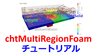
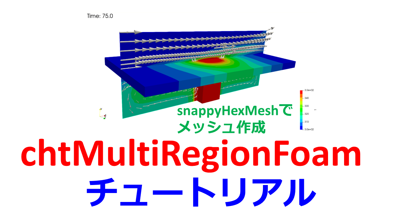
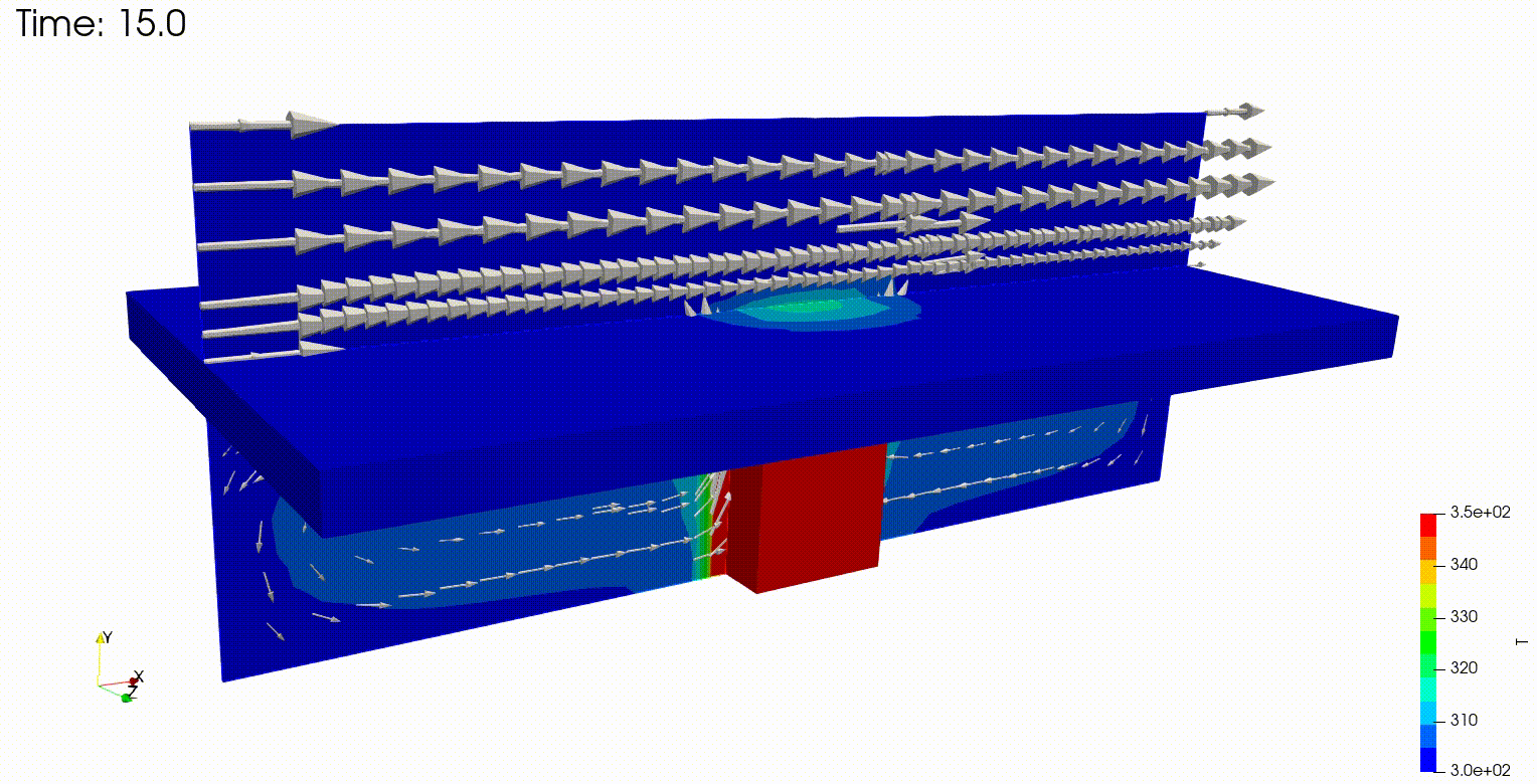
こんにちは(@t_kun_kamakiri)
OpenFOAMの熱流体固体連成のチュートリアルの解説を行います。
熱流体と熱伝導による固体の温度変化を解くソルバーを使います。
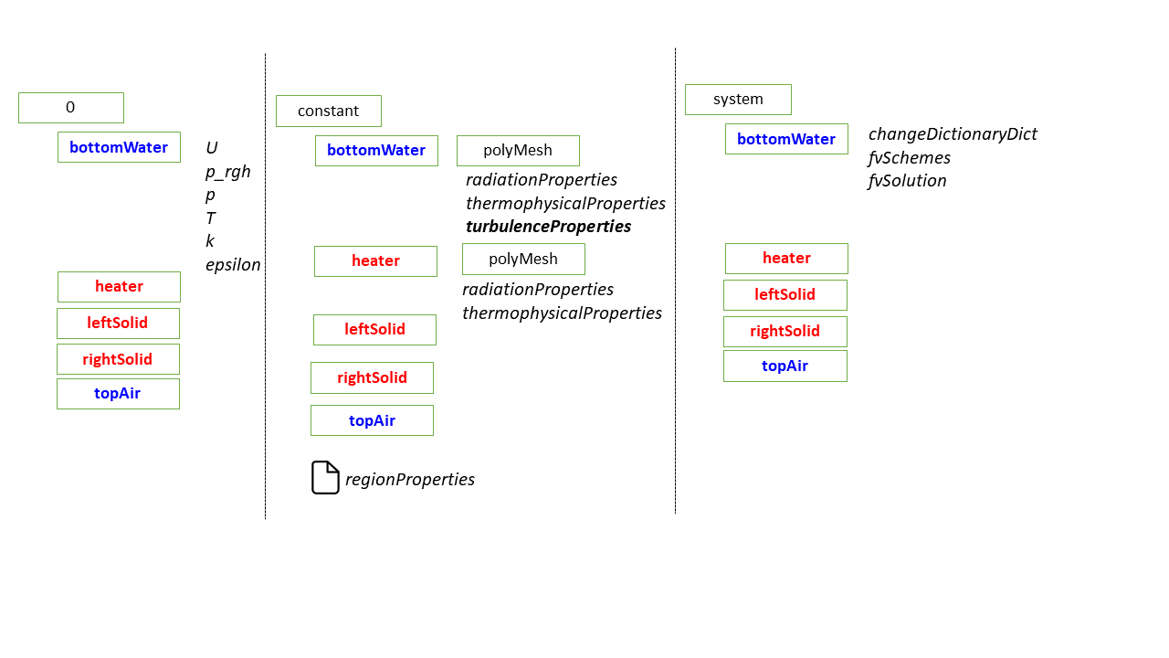
前回の記事では流体と固体の領域をtopoSetとsplitMeshRegionsで行いました。
- blockMesh:ベースメッシュの作成
- topoSet:cellZoneの作成
- cp -r 0.orig 0:0.origフォルダをコピー
- splitMeshRegions:topoSetで作成したcellZoneを使って領域分割
- changeDictionary:境界条件の変更
- chtMultiRegionFoam:計算実行
topoSetだと複雑な形状に対応できなかったり応用が利きづらいところがあります。
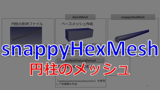
そこで、本記事ではsnappyHexMeshを使ったchtMultiRegionFoamのチュートリアルについてまとめておきます。
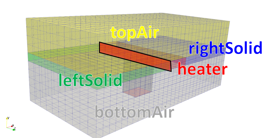
解析の設定は前回の記事と同じなので割愛します。
OpenFOAMv2036
熱流体固体連成のソルバ
今回は使うのは以下のようなソルバーです。
- chtMultiRegionFoam
- chtMultiRegionSimpleFoam
- chtMultiRegionTwoPhaseEulerFoam
chtMultiRegionFoamとchtMultiRegionSimpleFoamの違いはSimpleFoamと付いている方が定常解析用です。
本記事では非定常解析のchtMultiRegionFoamを使います。
チュートリアルをコピーする
チュートリアルをコピーします。
1 | cp -r $FOAM_TUTORIALS/heatTransfer/chtMultiRegionFoam/snappyMultiRegionHeater |
Allrunスクリプトを確認する
チュートリアルにはAllrunスクリプトが用意されているので、スクリプトの内容を確認すると必要な手順というのがわかります。
並列計算無し用のスクリプトとして「Allrun-serial」があるので、こちらを確認します。
並列計算用のスクリプトを見たい人は「Allrun-parallel」や「Allrun」をご確認ください。
Allrun-serial
1 2 3 4 5 6 7 8 9 10 11 12 13 14 15 16 17 18 19 20 21 22 23 24 25 26 27 28 29 30 31 | mkdir -p constant/triSurface cp -f "$FOAM_TUTORIALS"/resources/geometry/geom.stl.gz constant/triSurface rm -rf constant/polyMesh/sets runApplication blockMesh runApplication surfaceFeatureExtract runApplication snappyHexMesh -overwrite # Restore initial fields restore0Dir runApplication splitMeshRegions -cellZones -overwrite # Remove fluid fields from solid regions (important for post-processing) for region in $(foamListRegions solid) do rm -f 0/"$region"/{nut,alphat,epsilon,k,U,p_rgh} rm -f processor*/0/"$region"/{nut,alphat,epsilon,k,U,p_rgh} done for region in $(foamListRegions) do runApplication -s "$region" changeDictionary -region "$region" done # Run on single processor runApplication $(getApplication) |
では、中身を確認していきましょう。
stlファイルの入手
まずはこちらです。
「constant/triSurface」というフォルダを作成して、「geom.stl.gz」というstlファイルををコピーしています。
1 2 | mkdir -p constant/triSurface cp -f "$FOAM_TUTORIALS"/resources/geometry/geom.stl.gz constant/triSurface |
コピーしたファイルが圧縮ファイルなので以下のコマンドで解凍します。
1 | gzip -d constant/triSurface/*.gz |
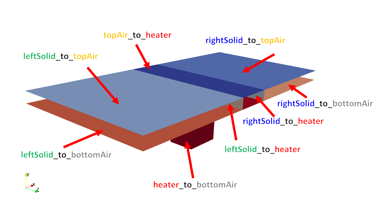
stlは各面をregionA_to_regionBのような形で書かれています。
geom.stl
1 2 3 4 5 6 7 8 9 10 11 12 13 14 15 16 17 18 | solid topAir_to_heater facet normal 0.000000000e+00 -1.000000000e+00 0.000000000e+00 outer loop vertex -1.333330000e-02 8.000000000e-03 -5.000000000e-02 vertex -6.666670000e-03 8.000000000e-03 -5.000000000e-02 vertex -6.666670000e-03 8.000000000e-03 -4.000000000e-02 endloop endfacet (省略) endsolid solid leftSolid_to_topAir (省略) endsolid solid rightSolid_to_topAir (省略) endsolid ... (省略) |
ParaViewで見るとこんな感じ。

FreeCADなどで面に名前を付けるのは簡単にできます。
blockMeshでメッシュ作成
blockMeshを実行します。
1 2 3 4 5 6 7 8 9 10 11 12 13 14 15 16 17 18 19 20 21 22 23 24 25 26 27 28 29 30 31 32 33 34 35 36 37 38 39 40 41 42 43 44 45 46 47 48 49 50 51 52 53 54 55 56 57 58 59 60 61 62 63 64 65 66 67 68 69 70 71 72 73 74 75 76 77 78 | scale 1; vertices ( (-0.1 -0.04 -0.05) ( 0.1 -0.04 -0.05) ( 0.1 0.04 -0.05) (-0.1 0.04 -0.05) (-0.1 -0.04 0.05) ( 0.1 -0.04 0.05) ( 0.1 0.04 0.05) (-0.1 0.04 0.05) ); blocks ( hex (0 1 2 3 4 5 6 7) (30 10 10) simpleGrading (1 1 1) ); edges ( ); boundary ( maxY { type wall; faces ( (3 7 6 2) ); } minX { type patch; faces ( (0 4 7 3) ); } maxX { type patch; faces ( (2 6 5 1) ); } minY { type wall; faces ( (1 5 4 0) ); } minZ { type wall; faces ( (0 3 2 1) ); } maxZ { type wall; faces ( (4 5 6 7) ); } ); mergePatchPairs ( ); |
以下のコマンドでベースメッシュを作成します。
1 | blockMesh |
surfaceFeatureExtract
続いてsltファイルを元に特徴線を作成します。
これは次のsnappyHexMeshで使用されます。
system/surfaceFeatureExtractDict
1 2 3 4 5 6 7 8 9 10 11 12 13 14 15 16 | geom.stl { extractionMethod extractFromSurface; // Mark edges whose adjacent surface normals are at an angle less // than includedAngle as features // - 0 : selects no edges // - 180: selects all edges includedAngle 150; // Write options writeFeatureEdgeMesh yes; // Write features to obj format for postprocessing writeObj yes; } |
snappyHexMesh
続いてstlファイルを元に形状に沿ってメッシュ作成します。
snappyHexMeshの中身は長いですが全部書いておきます。
system/snappyHexMeshDict
1 2 3 4 5 6 7 8 9 10 11 12 13 14 15 16 17 18 19 20 21 22 23 24 25 26 27 28 29 30 31 32 33 34 35 36 37 38 39 40 41 42 43 44 45 46 47 48 49 50 51 52 53 54 55 56 57 58 59 60 61 62 63 64 65 66 67 68 69 70 71 72 73 74 75 76 77 78 79 80 81 82 83 84 85 86 87 88 89 90 91 92 93 94 95 96 97 98 99 100 101 102 103 104 105 106 107 108 109 110 111 112 113 114 115 116 117 118 119 120 121 122 123 124 125 126 127 128 129 130 131 132 133 134 135 136 137 138 139 140 141 142 143 144 145 146 147 148 149 150 151 152 153 154 155 156 157 158 159 160 161 162 163 164 165 166 167 168 169 170 171 172 173 174 175 176 177 178 179 180 181 182 183 184 185 186 187 188 189 190 191 192 193 194 195 196 197 198 199 200 201 202 203 204 205 206 207 208 209 210 211 212 213 214 215 216 217 218 219 220 221 222 223 224 225 226 227 228 229 230 231 232 233 234 235 236 237 238 239 240 241 242 243 244 245 246 247 248 249 250 251 252 253 254 255 256 257 258 259 260 261 262 263 264 | // Which of the steps to run castellatedMesh true; snap true; addLayers false; // Geometry. Definition of all surfaces. All surfaces are of class // searchableSurface. // Surfaces are used // - to specify refinement for any mesh cell intersecting it // - to specify refinement for any mesh cell inside/outside/near // - to 'snap' the mesh boundary to the surface geometry { geom.stl { type triSurfaceMesh; name geom; } } // Settings for the castellatedMesh generation. castellatedMeshControls { // Refinement parameters // ~~~~~~~~~~~~~~~~~~~~~ // If local number of cells is >= maxLocalCells on any processor // switches from from refinement followed by balancing // (current method) to (weighted) balancing before refinement. maxLocalCells 100000; // Overall cell limit (approximately). Refinement will stop immediately // upon reaching this number so a refinement level might not complete. // Note that this is the number of cells before removing the part which // is not 'visible' from the keepPoint. The final number of cells might // actually be a lot less. maxGlobalCells 2000000; // The surface refinement loop might spend lots of iterations // refining just a few cells. This setting will cause refinement // to stop if <= minimumRefine are selected for refinement. Note: // it will at least do one iteration (unless the number of cells // to refine is 0) minRefinementCells 10; // Number of buffer layers between different levels. // 1 means normal 2:1 refinement restriction, larger means slower // refinement. nCellsBetweenLevels 2; // Explicit feature edge refinement // ~~~~~~~~~~~~~~~~~~~~~~~~~~~~~~~~ // Specifies a level for any cell intersected by its edges. // This is a featureEdgeMesh, read from constant/triSurface for now. features ( { file "geom.extendedFeatureEdgeMesh"; //"geom.eMesh"; level 1; } ); // Surface based refinement // ~~~~~~~~~~~~~~~~~~~~~~~~ // Specifies two levels for every surface. The first is the minimum level, // every cell intersecting a surface gets refined up to the minimum level. // The second level is the maximum level. Cells that 'see' multiple // intersections where the intersections make an // angle > resolveFeatureAngle get refined up to the maximum level. refinementSurfaces { geom { // Surface-wise min and max refinement level level (1 1); } } // Resolve sharp angles resolveFeatureAngle 30; // Region-wise refinement // ~~~~~~~~~~~~~~~~~~~~~~ // Specifies refinement level for cells in relation to a surface. One of // three modes // - distance. 'levels' specifies per distance to the surface the // wanted refinement level. The distances need to be specified in // descending order. // - inside. 'levels' is only one entry and only the level is used. All // cells inside the surface get refined up to the level. The surface // needs to be closed for this to be possible. // - outside. Same but cells outside. refinementRegions { //refinementBox //{ // mode inside; // levels ((1E15 4)); //} } // Mesh selection // ~~~~~~~~~~~~~~ // After refinement patches get added for all refinementSurfaces and // all cells intersecting the surfaces get put into these patches. The // section reachable from the locationInMesh is kept. // NOTE: This point should never be on a face, always inside a cell, even // after refinement. locationsInMesh ( (( 0.005 0.005 0.005) heater) (( 0.05 0.005 0.005) rightSolid) ((-0.05 0.005 0.005) leftSolid) ((-0.05 0.015 0.005) topAir) ((-0.05 -0.015 0.005) bottomAir) ); // Whether any faceZones (as specified in the refinementSurfaces) // are only on the boundary of corresponding cellZones or also allow // free-standing zone faces. Not used if there are no faceZones. allowFreeStandingZoneFaces false; } // Settings for the snapping. snapControls { //- Number of patch smoothing iterations before finding correspondence // to surface nSmoothPatch 3; //- Relative distance for points to be attracted by surface feature point // or edge. True distance is this factor times local // maximum edge length. tolerance 1.0; //- Number of mesh displacement relaxation iterations. nSolveIter 30; //- Maximum number of snapping relaxation iterations. Should stop // before upon reaching a correct mesh. nRelaxIter 5; //- Highly experimental and wip: number of feature edge snapping // iterations. Leave out altogether to disable. // Of limited use in this case since faceZone faces not handled. nFeatureSnapIter 10; } // Settings for the layer addition. addLayersControls { relativeSizes true; // Per final patch (so not geometry!) the layer information layers { maxY { nSurfaceLayers 3; } } // Expansion factor for layer mesh expansionRatio 1.3; // Wanted thickness of final added cell layer. If multiple layers // is the thickness of the layer furthest away from the wall. // Relative to undistorted size of cell outside layer. // See relativeSizes parameter. finalLayerThickness 1; // Minimum thickness of cell layer. If for any reason layer // cannot be above minThickness do not add layer. // Relative to undistorted size of cell outside layer. minThickness 0.1; // If points get not extruded do nGrow layers of connected faces that are // also not grown. This helps convergence of the layer addition process // close to features. // Note: changed(corrected) w.r.t 1.7.x! (didn't do anything in 1.7.x) nGrow 0; // Advanced settings // When not to extrude surface. 0 is flat surface, 90 is when two faces // are perpendicular featureAngle 30; // Maximum number of snapping relaxation iterations. Should stop // before upon reaching a correct mesh. nRelaxIter 3; // Number of smoothing iterations of surface normals nSmoothSurfaceNormals 1; // Number of smoothing iterations of interior mesh movement direction nSmoothNormals 3; // Smooth layer thickness over surface patches nSmoothThickness 2; // Stop layer growth on highly warped cells maxFaceThicknessRatio 0.5; // Reduce layer growth where ratio thickness to medial // distance is large maxThicknessToMedialRatio 1; // Angle used to pick up medial axis points // Note: changed(corrected) w.r.t 1.7.x! 90 degrees corresponds to 130 // in 1.7.x. minMedialAxisAngle 90; // Create buffer region for new layer terminations nBufferCellsNoExtrude 0; // Overall max number of layer addition iterations. The mesher will exit // if it reaches this number of iterations; possibly with an illegal // mesh. nLayerIter 50; } // Generic mesh quality settings. At any undoable phase these determine // where to undo. meshQualityControls { #include "meshQualityDict" // Advanced //- Number of error distribution iterations nSmoothScale 4; //- Amount to scale back displacement at error points errorReduction 0.75; } // Advanced // Merge tolerance. Is fraction of overall bounding box of initial mesh. // Note: the write tolerance needs to be higher than this. mergeTolerance 1e-6; |
大事なのはcastellatedMeshControlsの{}の中の以下の部分です。
1 2 3 4 5 6 7 8 | locationsInMesh ( (( 0.005 0.005 0.005) heater) (( 0.05 0.005 0.005) rightSolid) ((-0.05 0.005 0.005) leftSolid) ((-0.05 0.015 0.005) topAir) ((-0.05 -0.015 0.005) bottomAir) ); |
これによりsnappyHexMeshを実行するとstl面で区切られた部分の領域は名前が付けられたcellZoneができます。
1 | snappyHexMesh -overwrite |
constant/polyMesh/cellZones
1 2 3 4 5 6 7 8 9 10 11 12 13 14 15 16 17 18 19 20 21 22 23 24 | 5 (heater { type cellZone; cellLabels List<label> 640 ... (省略) ... 163 166 ) ; } leftSolid { type cellZone; cellLabels List<label> 1040 ( 150 ... (省略) ... |
こんな形でできています。
ParaViewで確認することもできます。


※以下補足です。
snappyHexMeshはstlファイルで区切られた領域のメッシュを作成するために、locationInMeshを使うことがあります。
試しに上記をコメントアウトして以下のようにしてsnappyHexMeshを実行してみます。
1 2 3 4 5 6 7 8 9 10 | // (( 0.005 0.005 0.005) heater) // (( 0.05 0.005 0.005) rightSolid) // ((-0.05 0.005 0.005) leftSolid) // ((-0.05 0.015 0.005) topAir) // ((-0.05 -0.015 0.005) bottomAir) // ); locationInMesh ( 0.005 0.005 0.005 ); |
これだとheaterの部分しか作られていないですね。
splitMeshRegions :各領域に分割
まずは0.origをコピーして0フォルダを作ります。
1 | cp -r 0.orig |
splitMeshRegionsを行う前に必ず0フォルダを作成する必要があります。
では、splitMeshRegionsを実行してsnappyHexMeshで作成したcellZoneを使って領域の分割を行います。
1 | splitMeshRegions -cellZones -overwrite |
ParaViewで確認。
constant/bottomAir/polyMesh/boundary
1 2 3 4 5 6 7 8 9 10 11 12 13 14 15 16 17 18 19 20 21 22 23 24 25 26 27 28 29 30 31 32 33 34 35 36 37 38 39 40 41 42 43 44 45 46 47 48 49 50 51 52 53 54 55 56 57 58 59 60 61 62 63 64 65 66 67 68 69 70 71 72 73 74 | 8 ( minX { type wall; nFaces 80; startFace 11196; } maxX { type wall; nFaces 80; startFace 11276; } minY { type wall; inGroups 1 ( wall ); nFaces 340; startFace 11356; } minZ { type wall; inGroups 1 ( wall ); nFaces 240; startFace 11696; } maxZ { type wall; inGroups 1 ( wall ); nFaces 240; startFace 11936; } bottomAir_to_rightSolid { type mappedWall; inGroups 1 ( wall ); nFaces 520; startFace 12176; sampleMode nearestPatchFace; sampleRegion rightSolid; samplePatch rightSolid_to_bottomAir; } bottomAir_to_leftSolid { type mappedWall; inGroups 1 ( wall ); nFaces 520; startFace 12696; sampleMode nearestPatchFace; sampleRegion leftSolid; samplePatch leftSolid_to_bottomAir; } bottomAir_to_heater { type mappedWall; inGroups 1 ( wall ); nFaces 368; startFace 13216; sampleMode nearestPatchFace; sampleRegion heater; samplePatch heater_to_bottomAir; } ) |
以下のような構造になっています。
1 2 3 4 5 6 7 8 9 10 | regionA_to_regionB { type mappedWall; inGroups 1(wall); nFaces 130; startFace 4550; sampleMode nearestPatchFace; sampleRegion regionA; samplePatch regionB_to_regionA; } |
typeはmappedWallとしておく必要があります。
あとの境界の設定は前回の記事と同じです。
別のページ開くのも面倒だと思いますので以下に書いておきます。
境界条件の設定
Allrun.preを見ると以下のような記述があります。
1 2 3 4 5 6 | # Remove fluid fields from solid regions (important for post-processing) for region in $(foamListRegions solid) do rm -f 0/$region/{nut,alphat,epsilon,k,U,p_rgh} rm -f processor*/0/$region/{nut,alphat,epsilon,k,U,p_rgh} done |
foamListRegionsが「constant/regionProperties」で指定しているリストをします。
1 2 3 4 5 | regions ( fluid (bottomWater topAir) solid (heater leftSolid rightSolid) ); |
foamListRegionsだけだと領域全ての要素をリストにするので、 [bottomWater topAir heater leftSolid rightSolid]というリストになります。
しかし以下のようにregionTypeを指定すると、
1 | foamListRegions [OPTIONS] [regionType ... regionType] |
「foamListRegions solid」とsolidを指定するとsolidだけを要素にするので [heater leftSolid rightSolid]となります。
つまり、上記のdo文は以下のようになります。
1 2 3 4 5 6 | rm -f 0/heater/{nut,alphat,epsilon,k,U,p_rgh} rm -f processor*/0/heater/{nut,alphat,epsilon,k,U,p_rgh} rm -f 0/leftSolid/{nut,alphat,epsilon,k,U,p_rgh} rm -f processor*/0/leftSolid/{nut,alphat,epsilon,k,U,p_rgh} rm -f 0/rightSolid/{nut,alphat,epsilon,k,U,p_rgh} rm -f processor*/0/rightSolid/{nut,alphat,epsilon,k,U,p_rgh} |
既に設定がされていたら設定を消すためものですね。
「rm -f」の「-f」オプションはファイルがあれば削除するというものです。
続いてAllrun.preを見ると以下のようになっています。
1 2 3 4 | for region in $(foamListRegions) do runApplication -s $region changeDictionary -region $region done |
これはsystemフォルダ内で各領域のフォルダ内を用意しその中にchangeDictionaryを用意して境界条件の設定を変更していきます。
system/bottomAir/changeDictionaryDict
1 2 3 4 5 6 7 8 9 10 11 12 13 14 15 16 17 18 19 20 21 22 23 24 25 26 27 28 29 30 31 32 33 34 35 36 37 38 39 40 41 42 43 44 45 46 47 48 49 50 51 52 53 54 55 56 57 58 59 60 61 62 63 64 65 66 67 68 69 70 71 72 73 74 75 76 77 78 79 80 81 82 83 84 85 86 87 88 89 90 91 92 93 94 95 96 97 98 99 100 101 102 103 104 105 106 107 108 109 110 111 112 113 114 115 116 117 118 119 120 121 122 123 124 125 126 127 128 129 | boundary { minX { type wall; } maxX { type wall; } } U { internalField uniform (0.01 0 0); boundaryField { ".*" { type fixedValue; value uniform (0 0 0); } "procBoundary.*" { type processor; } } } T { internalField uniform 300; boundaryField { ".*" { type zeroGradient; } "procBoundary.*" { type processor; } "bottomAir_to_.*" { type compressible::turbulentTemperatureRadCoupledMixed; Tnbr T; kappaMethod fluidThermo; value uniform 300; } } } epsilon { // Set the value on all bc to non-zero. Not used in simulation // since zeroGradient; only used in initialisation. internalField uniform 0.01; boundaryField { ".*" { type epsilonWallFunction; value uniform 0.01; } "procBoundary.*" { type processor; } } } k { internalField uniform 0.1; boundaryField { ".*" { type kqRWallFunction; value uniform 0.1; } "procBoundary.*" { type processor; } } } p_rgh { internalField uniform 1e5; boundaryField { ".*" { type fixedFluxPressure; value uniform 1e5; } "procBoundary.*" { type processor; } } } p { internalField uniform 1e5; boundaryField { ".*" { type calculated; value uniform 1e5; } "procBoundary.*" { type processor; } } } |
上記のスクリプトでchangeDictionaryが実行されると、以下のようにファイルが作成されます。
各領域がどの様に変更されたのかを見ていきます。
0/bottomAir/U
1 2 3 4 5 6 7 8 9 10 11 12 13 14 15 16 17 18 19 20 21 22 23 24 25 26 27 28 29 30 31 32 33 34 35 36 37 38 39 40 41 42 43 44 45 46 47 48 49 50 51 | dimensions [ 0 1 -1 0 0 0 0 ]; internalField uniform ( 0.001 0 0 ); boundaryField { minX { // before changeDictionary // type calculated; // value uniform (0.01 0 0); type fixedValue; value uniform ( 0.001 0 0 ); } maxX { type inletOutlet; value uniform ( 0.01 0 0 ); inletValue uniform ( 0 0 0 ); } minY { type fixedValue; value uniform ( 0 0 0 ); } minZ { type fixedValue; value uniform ( 0 0 0 ); } maxZ { type fixedValue; value uniform ( 0 0 0 ); } bottomWater_to_rightSolid { type fixedValue; value uniform ( 0 0 0 ); } bottomWater_to_leftSolid { type fixedValue; value uniform ( 0 0 0 ); } bottomWater_to_heater { type fixedValue; value uniform ( 0 0 0 ); } } |
0/bottomAir/T
1 2 3 4 5 6 7 8 9 10 11 12 13 14 15 16 17 18 19 20 21 22 23 24 25 26 27 28 29 30 31 32 33 34 35 36 37 38 39 40 41 42 43 44 45 46 47 48 49 50 51 52 53 | dimensions [ 0 0 0 1 0 0 0 ]; internalField uniform 300; boundaryField { minX { type zeroGradient; value uniform 300; } maxX { type zeroGradient; value uniform 300; } minY { type zeroGradient; value uniform 300; } minZ { type zeroGradient; value uniform 300; } maxZ { type zeroGradient; value uniform 300; } bottomAir_to_rightSolid { type compressible::turbulentTemperatureRadCoupledMixed; value uniform 300; Tnbr T; kappaMethod fluidThermo; } bottomAir_to_leftSolid { type compressible::turbulentTemperatureRadCoupledMixed; value uniform 300; Tnbr T; kappaMethod fluidThermo; } bottomAir_to_heater { type compressible::turbulentTemperatureRadCoupledMixed; value uniform 300; Tnbr T; kappaMethod fluidThermo; } } |
1 2 3 4 5 6 7 8 9 10 11 12 13 14 15 16 17 18 19 20 21 22 23 24 25 26 27 28 29 30 31 32 33 34 35 36 37 38 39 40 41 42 43 | dimensions [ 0 0 0 1 0 0 0 ]; internalField uniform 300; boundaryField { minX { type zeroGradient; value uniform 300; } minZ { type zeroGradient; value uniform 300; } maxZ { type zeroGradient; value uniform 300; } leftSolid_to_bottomAir { type compressible::turbulentTemperatureRadCoupledMixed; value uniform 300; Tnbr T; kappaMethod solidThermo; } leftSolid_to_heater { type compressible::turbulentTemperatureRadCoupledMixed; value uniform 300; Tnbr T; kappaMethod solidThermo; } leftSolid_to_topAir { type compressible::turbulentTemperatureRadCoupledMixed; value uniform 300; Tnbr T; kappaMethod solidThermo; } } |
以下のように熱伝導率を持つ厚みにある境界面を挟むことができます。
前回の記事で紹介したチュートリアルは以下のようになっていました。
1 2 3 4 5 6 7 8 9 10 11 12 13 14 15 16 17 18 19 20 21 22 23 24 25 26 27 28 29 30 31 32 33 34 35 36 37 38 39 40 41 42 43 44 45 | dimensions [ 0 0 0 1 0 0 0 ]; internalField uniform 300; boundaryField { minX { type zeroGradient; value uniform 300; } minZ { type zeroGradient; value uniform 300; } maxZ { type zeroGradient; value uniform 300; } leftSolid_to_bottomWater { type compressible::turbulentTemperatureRadCoupledMixed; value uniform 300; Tnbr T; kappaMethod solidThermo; } leftSolid_to_heater { type compressible::turbulentTemperatureRadCoupledMixed; value uniform 300; Tnbr T; kappaMethod solidThermo; thicknessLayers ( 0.001 ); kappaLayers ( 0.0005 ); } leftSolid_to_topAir { type compressible::turbulentTemperatureRadCoupledMixed; value uniform 300; Tnbr T; kappaMethod solidThermo; } } |
- thicknessLayersで厚みを0.001[m]
- kappaLayersで熱伝導率を0.005[W/m K]
この辺の違いも確認しておくと良いですね。
設定のまとめ

- blockMesh:ベースメッシュの作成
- surfaceFeatureExtract:特徴線の抽出
- snappyHexMesh:stlに沿ったメッシュ作成、cellZoneの作成
- cp -r 0.orig 0:0.origフォルダをコピー
- splitMeshRegions:snappyHexMeshで作成したcellZoneを使って領域分割
- changeDictionary:境界条件の変更
ここまでまとめてきて、これを手作業で行うのは至難の業ですね。
なので、オリジナルの解析を行う際はスクリプトを使うことは必須になります。
計算実行
設定の確認ができたので計算を実行します。
system/controlDictは以下のようになっています。
system/controlDict
1 2 3 4 5 6 7 8 9 10 11 12 13 14 15 16 17 18 19 20 21 22 23 24 25 26 27 28 29 30 31 32 33 34 35 36 37 38 39 40 41 | application chtMultiRegionFoam; startFrom latestTime; startTime 0.001; stopAt endTime; endTime 100; deltaT 0.001; writeControl adjustable; writeInterval 10; purgeWrite 0; writeFormat ascii; writePrecision 8; writeCompression off; timeFormat general; timePrecision 6; runTimeModifiable yes; maxCo 0.6; // Maximum diffusion number maxDi 10.0; adjustTimeStep yes; functions { #include "vtkWrite" } |
function Objectsで「#include “vtkWrite”」として、「system/vtkWrite」ファイルを読み込んでいます。
今回のチュートリアルにはこちらの記述が無いので追加しておきます。
各領域のvtkファイルを作成してくれているのでParaViewで結果を確認するときは便利です。
system/vtkWrite
1 2 3 4 5 6 7 8 9 10 11 12 13 14 15 16 17 18 19 20 21 22 23 24 25 26 27 28 29 30 31 32 33 34 35 36 37 38 39 40 41 42 43 44 45 46 47 48 49 50 51 52 53 54 55 | vtkWrite { type vtkWrite; libs (utilityFunctionObjects); log true; writeControl writeTime; writeInterval 1; regions (".*"); internal true; boundary true; single false; interpolate true; // Fields to output (words or regex) fields (".*"); //- Output format (ascii | binary) - Default=binary // format binary; //- Use legacy output format - Default=false // legacy false; //- Output directory name - Default="postProcessing/<name>" // directory "VTK"; //- Write cell ids as field - Default=true writeIds false; } // Solid walls only walls { type vtkWrite; libs (utilityFunctionObjects); log true; writeControl writeTime; writeInterval 1; internal false; // single true; regions ( heater "(?i).*solid" ); patches ( "(?i).*solid_to.*" "heater.*(Air|Water)" ); fields (T); } |
では、計算実行します。
1 | chtMultiRegionFoam |
結果の確認
ParaViewでpostProcessingに保存されたvtkファイルを読み込みます。

前回の記事では、leftSolidとheaterの境界は熱伝導率を持つ厚みを設けたので熱が伝わりにくくなっているのが確認できます。leftSolidの熱の伝わり方が違いますね。

まとめ
OpenFOAMのchtmultiRegionFoamのチュートリアルの解説を行いました。
手順は以下です。
- blockMesh:ベースメッシュの作成
- topoSet:cellZoneの作成
- cp -r 0.orig 0:0.origフォルダをコピー
- splitMeshRegions:topoSetで作成したcellZoneを使って領域分割
- changeDictionary:境界条件の変更
- chtMultiRegionFoam:計算実行
これでだいたいの使い方はわかりましたので、オリジナルの解析などをしたいですね。
chtMultiRegionFoamの勉強のきっかけ
当ブログに低温調理でのお肉の温度変化を対流なども考慮した解析をできないかという問い合わせが来ました。
- 複数の物質との熱伝導
- 強制対流や自然対流も考慮した熱解析
- 脂肪の融解熱
など考慮したいことが多いようです。
あまり色々と考えたあげく以下のように提案をしてみました。

- 方法1
熱流体は個別でOpenFOAMなりで計算して熱流束や熱伝達率を算出する
その熱流束や熱伝達率を固体表面に与えて熱解析を行う - 方法2
本記事で紹介したように流体・固体熱連成を行う
というわけで、方法2を試すことにしました。
どれほどchtMultiRegionFoamソルバが使えるのかを試してみたくなったというわけです。
※追記:適当な条件で試しました。
適当にモデルを作ってやってみました。
物性は良くわからないですが調べて適当に設定しています。
constant/solid/thermophysicalProperties
1 2 3 4 5 6 7 8 9 10 11 12 13 14 15 16 17 18 19 20 21 22 23 24 25 26 27 28 29 30 31 32 33 34 35 36 37 38 | thermoType { type heSolidThermo; mixture pureMixture; transport constIso; thermo hConst; equationOfState rhoConst; specie specie; energy sensibleEnthalpy; } /* 脂肪層の熱特性 熱伝導率は水の1/3の0.194[W/m・K] 比熱容量は水の1/2の2.09[kJ/kg・K] 比重は0.92g/ml */ mixture { specie { molWeight 6000;//g/mol } transport { kappa 0.194;// W/m K } thermodynamics { Hf 0; Cp 2.09E3; //J/kg K } equationOfState { rho 920;//kg/m3 } } |
おすすめ参考図書
☟こちらは、OpenFOAMの日本語書籍が無い中唯一わかりやすい参考書だと思います。
☟こちらもOpenFOMの古いバージョンでの和訳になります。さすがにこちらはバージョンに対する日本語でのケアはしていないので、OpenFOAMに慣れている方は購入しても良いかと思います。僕は「日本語でまとまっている内容」なので少し重宝しています。
☟以下に、もっと初心者向けの同人誌を紹介しておきます。
初心者は「ってか、まずどうやってOpenFOAMをインストールするの?」というところからつまずきがちです。
そんな時は、以下の書籍をおすすめします。
改訂新版 OpenFOAMの歩き方 (技術の泉シリーズ(NextPublishing))
インストール方法とチュートリアルで流体解析を体験・・・ちょっと高度な解析まで解説があります。著者曰くOpenFOAMのバージョンの追跡を行いながら、書籍をアップデートするようなので安心ですね。