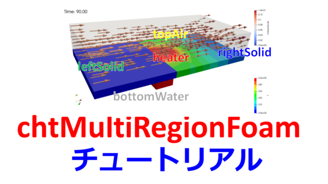
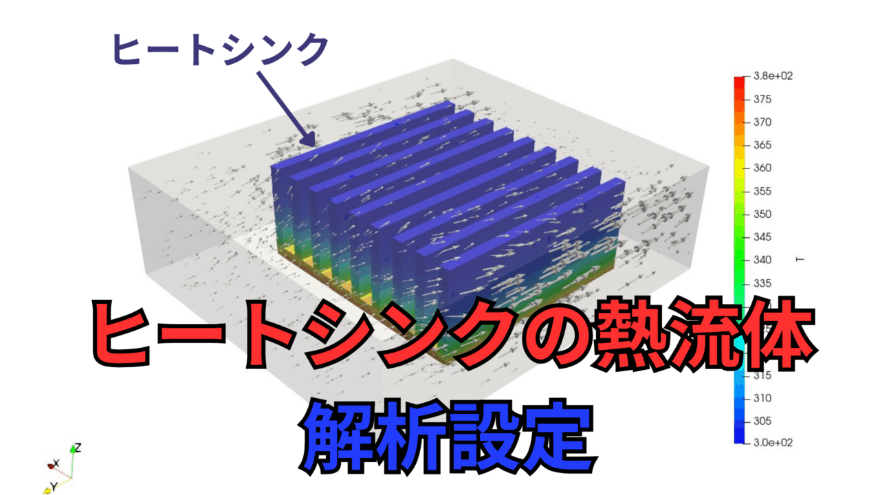
【ヒートシンクの熱流体(2)】OpenFOAMの熱流体固体連成の計算実行
こんにちは(@t_kun_kamakiri)
OpenFOAMの熱流体固体連成によるヒートシンクの熱流体解析の設定方法を解説します。
使用するソルバはchtMultiRegionSimpleFoamで熱流体と固体を連成させた定常解析用のソルバになります。
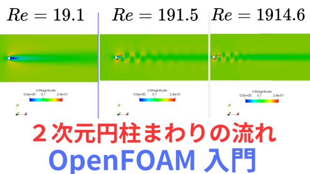
本記事ではヒートシンクの熱流体解析を行います。
CFDで移動現象論111例題
ヒートシンクhttps://t.co/ceod0EWiq6 https://t.co/pz65L8pkjU pic.twitter.com/B4F6EO3UOb— カマキリ🐲計算力学頑張る (@t_kun_kamakiri) August 4, 2025
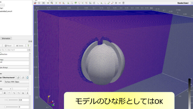
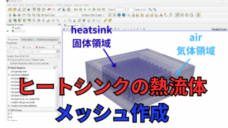
前回の記事ではヒートシンクの熱流体解析を行うにあたってのメッシュ作成を解説しました。
chtMultiRegionSimpleFoamによるヒートシンクの熱流体(固体連成)解析の設定方法を示す
ただ、テキストベースで解析設定しようとすると、めちゃくちゃ大変です。
以下にOpenFOAMが用意しているチュートリアルを解説した記事がありますので、一度読んでみると良いでしょう。
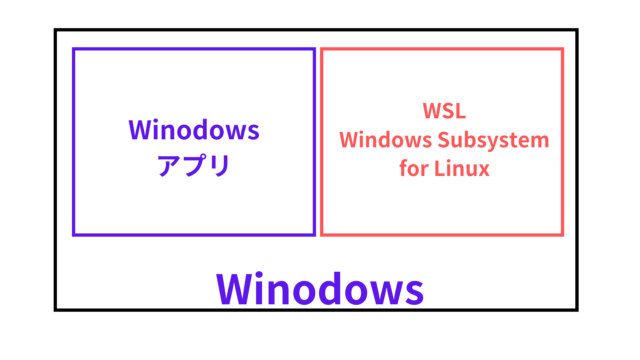
OpenFOAM v2412(WSL Ubuntu 22.04)
境界条件の設定
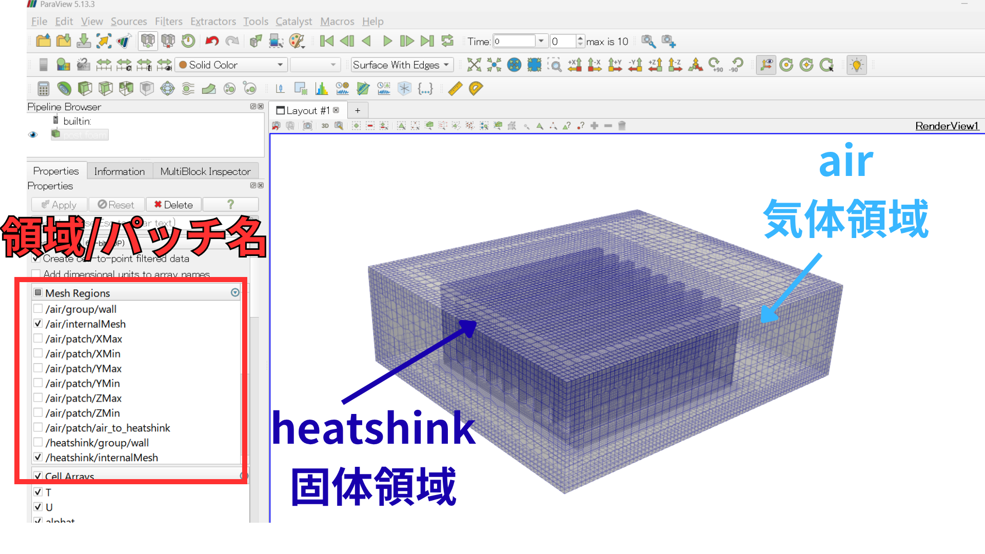
前回の記事で以下のコマンドにより気体・固体領域の分割を行いました。
|
1 |
splitMeshRegions -cellZones -overwrite |
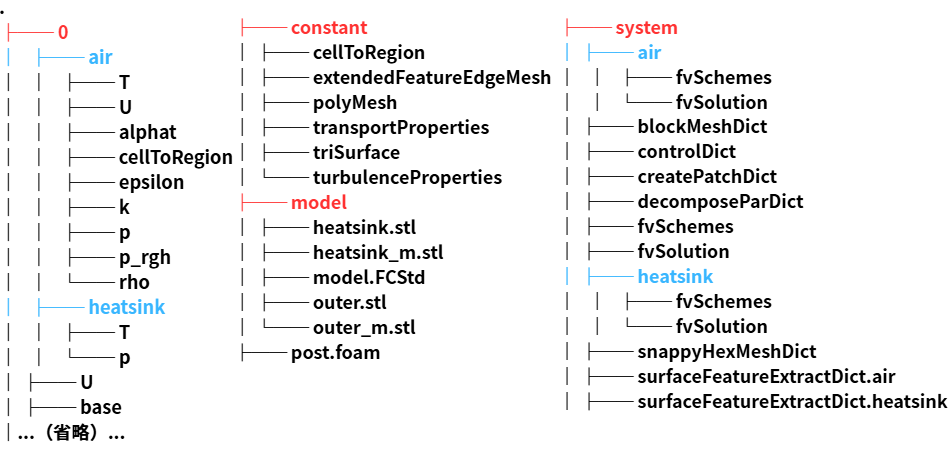
領域分割によりフォルダ構成は以下となっています。
splitMeshRegionsコマンドにより、0, constant. system内に領域ごとの設定ファイルが作成されますconstant/air(heatsink), system/air(heatsink)のフォルダは元々作成していましたが、0/air(heatsink)はフォルダが生成されたと思います。
気体領域と固体領域で共通している面は、heatsink_to_airやair_to_heatsinkの名前が付けられます。
….という内容までを前回の記事で行いました。
|
1 |
cp -r $FOAM_TUTORIALS/heatTransfer/chtMultiRegionFoam/externalSolarLoad/0.orig/air/nut 0/ |
0/nutは以下に編集します。
0/nut
|
1 2 3 4 5 6 7 8 9 10 11 12 13 14 |
dimensions [0 2 -1 0 0 0 0]; internalField uniform 0; boundaryField { #includeEtc "caseDicts/setConstraintTypes" ".*" { type calculated; value $internalField; } } |
続いて物性値を設定します。
物性値の設定
まずは気体領域の設定です。
consant/air/thermophysicalProperties
|
1 2 3 4 5 6 7 8 9 10 11 12 13 14 15 16 17 18 19 20 21 22 23 24 25 26 27 28 |
thermoType { type heRhoThermo; mixture pureMixture; transport const; thermo hConst; equationOfState perfectGas; specie specie; energy sensibleEnthalpy; } mixture { specie { molWeight 28.9; } thermodynamics { Cp 1000; Hf 0; } transport { mu 1.8e-05; Pr 0.7; } } |
equationOfState perfectGas;としているので密度$\rho$は理想気体の状態方程式$p=\rho RT$により圧力$p$と温度$T$から計算されます。
固体領域の設定を行います。
consant/heatsink/thermophysicalProperties
|
1 2 3 4 5 6 7 8 9 10 11 12 13 14 15 16 17 18 19 20 21 22 23 24 25 26 27 28 29 30 31 |
thermoType { type heSolidThermo; mixture pureMixture; transport constIso; thermo hConst; equationOfState rhoConst; specie specie; energy sensibleEnthalpy; } mixture { specie { molWeight 12; } transport { kappa 80; } thermodynamics { Hf 0; Cp 450; } equationOfState { rho 8000; } } |
乱流モデルの設定
乱流モデルは流体領域だけに設定するのでconstant/air/turbulencePropertiesだけに設定します。
ただ今回$k$-$\varepsilon$モデルを使用するとエラーになったので乱流モデルは使用しないことにします。
|
1 2 3 4 5 6 7 8 9 10 11 |
simulationType laminar; // simulationType RAS; // RAS // { // RASModel kEpsilon; // turbulence on; // printCoeffs on; // } |
値の設定の問題かもしれないので本記事ではいちおう乱流モデルの設定として記載しておきます。
境界条件の設定
いよいよ境界条件の設定を行います。
境界条件のフォルダは0フォルダにありますが、マルチリージョン系は複数の領域に境界条件が分かれており、それぞれ設定する必要があります。
これが結構めんどう…
例えば、0/air/Uを確認してみます。
0/air/U
|
1 2 3 4 5 6 7 8 9 10 11 12 13 14 15 16 17 18 19 20 21 22 23 24 25 26 27 28 29 30 31 32 33 34 35 36 37 38 39 40 41 42 |
dimensions [0 1 -1 0 0 0 0]; internalField uniform (0.01 0 0); boundaryField { XMin { type calculated; value uniform (0.01 0 0); } YMin { type calculated; value uniform (0.01 0 0); } ZMax { type calculated; value uniform (0.01 0 0); } YMax { type calculated; value uniform (0.01 0 0); } ZMin { type calculated; value uniform (0.01 0 0); } XMax { type calculated; value uniform (0.01 0 0); } air_to_heatsink { type calculated; value uniform (0 0 0); } } |
まだ適切な境界条件が設定されていませんが、ひとつずつ適切な境界条件を設定する必要があります。マルチリージョン系のチュートリアルを見ると、だいたいchangeDictionaryを使って境界条件を変更しているので、そちらに倣います。
changeDictionary
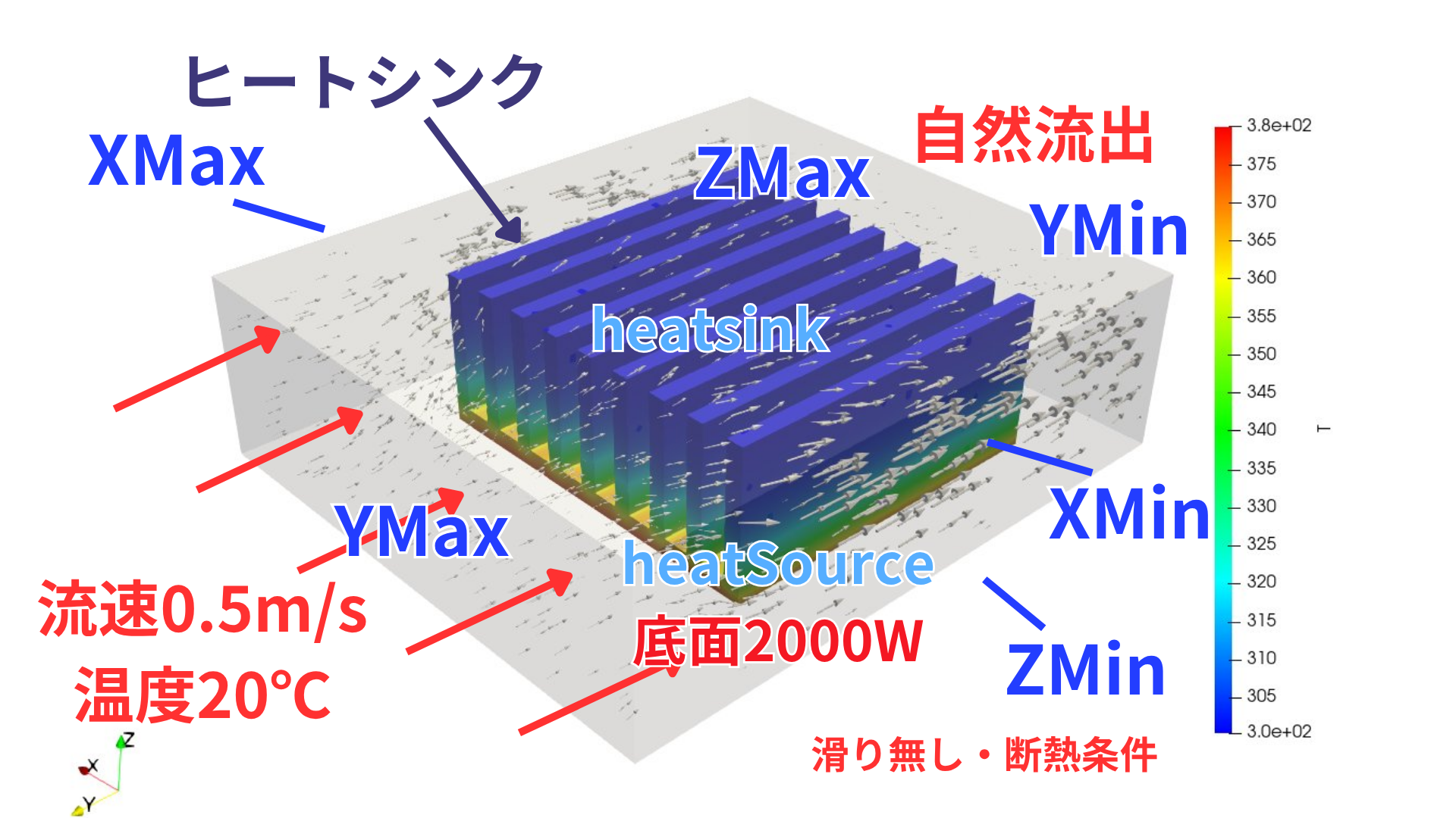
どういう境界条件にするかは絵を描いて抑えておくと良いでしょう。
まずは気体領域から。
system/air/changeDictionary
|
1 2 3 4 5 6 7 8 9 10 11 12 13 14 15 16 17 18 19 20 21 22 23 24 25 26 27 28 29 30 31 32 33 34 35 36 37 38 39 40 41 42 43 44 45 46 47 48 49 50 51 52 53 54 55 56 57 58 59 60 61 62 63 64 65 66 67 68 69 70 71 72 73 74 75 76 77 78 79 80 81 82 83 84 85 86 87 88 89 90 91 92 93 94 95 96 97 98 99 100 101 102 103 104 105 106 107 108 109 110 111 112 113 114 115 116 117 118 119 120 121 122 123 124 125 126 127 128 129 130 131 132 133 134 135 136 137 138 139 140 141 142 143 144 145 146 147 148 149 150 151 152 153 154 155 156 157 158 159 160 161 162 163 164 165 166 167 168 169 170 171 172 173 174 175 176 177 178 179 180 181 182 183 184 185 186 187 188 189 190 191 192 193 194 195 196 197 198 199 200 201 202 203 204 205 206 207 208 209 210 211 212 213 214 215 216 217 218 219 220 221 |
boundary { XMin { type wall; } XMax { type wall; } YMin { type patch; } YMax { type patch; } ZMin { type wall; } ZMax { type wall; } air_to_heatsink { type mappedWall; sampleMode nearestPatchFace; sampleRegion heatsink; samplePatch heatsink_to_air; } } U { internalField uniform (0 -0.5 0); boundaryField { "(XMin|XMax|ZMin|ZMax)" { type noSlip; } YMin { // type zeroGradient; type pressureInletOutletVelocity; value $internalField; } YMax { type fixedValue; value $internalField; } "air_to_.*" { type fixedValue; value uniform (0 0 0); } // "procBoundary.*" // { // type processor; // } } } T { internalField uniform 293.15; boundaryField { "(XMin|XMax|ZMin|ZMax|YMin)" { type zeroGradient; } YMax { type fixedValue; value uniform 293.15; // 20 degC } // "procBoundary.*" // { // type processor; // } "air_to_.*" { type compressible::turbulentTemperatureRadCoupledMixed; Tnbr T; kappaMethod fluidThermo; value uniform 293.15; } } } p_rgh { internalField uniform 1e5; boundaryField { ".*" { type fixedFluxPressure; value uniform 1e5; } YMin { type totalPressure; p0 uniform 100000; value uniform 100000; } // "procBoundary.*" // { // type processor; // } } } p { internalField uniform 1e5; boundaryField { ".*" { type calculated; value uniform 1e5; } // "procBoundary.*" // { // type processor; // } } } epsilon { // Set the value on all bc to non-zero. Not used in simulation // since zeroGradient; only used in initialisation. internalField uniform 0.01; boundaryField { ".*" { type epsilonWallFunction; value uniform 0.01; } YMin { type inletOutlet; inletValue uniform 1.35e-05; value uniform 1.35e-13; } YMax { type turbulentMixingLengthDissipationRateInlet; mixingLength 0.01; // 1cm - half channel height value $internalField; } // "procBoundary.*" // { // type processor; // } } } k { internalField uniform 0.1; boundaryField { ".*" { type epsilonWallFunction; value uniform 0.01; } YMin { type inletOutlet; inletValue uniform 1.35e-05; value uniform 1.35e-13; } YMax { type turbulentIntensityKineticEnergyInlet; intensity 0.03; value $internalField; } // "procBoundary.*" // { // type processor; // } } } alphat { internalField uniform 0; boundaryField { ".*" { type compressible::alphatWallFunction; Prt 0.85; value uniform 0; } // "procBoundary.*" // { // type processor; // } } } |
乱流モデルを使用しない場合は、必要になるのはU, T, p_rgh, pのみですが、乱流モデル用の設定の記載をしておきます。
続いて固体領域。
system/heatsink/changeDictionary
|
1 2 3 4 5 6 7 8 9 10 11 12 13 14 15 16 17 18 19 20 21 22 23 24 25 26 27 28 29 30 31 32 33 34 35 36 37 38 39 40 41 42 43 44 |
boundary { heatSource { type wall; } heatshink_to_air { type mappedWall; sampleMode nearestPatchFace; sampleRegion air; samplePatch air_to_heatshink; } } T { internalField uniform 293.15; boundaryField { heatSource { type externalWallHeatFluxTemperature; kappaMethod solidThermo; mode power;//flux; Ta $internalField; Q uniform 2000; value $internalField; kappaName none; // thicknessLayers ( 1 2 ); // kappaLayers ( 100 200 ) } heatsink_to_air { type compressible::turbulentTemperatureRadCoupledMixed; Tnbr T; kappaMethod solidThermo; // thicknessLayers ( 0.001 ); // kappaLayers ( 0.0005 ); } } } |
以下のコマンドを実行します。
|
1 2 |
changeDictionary -region air changeDictionary -region heatsink |
境界条件設定のファイルの中身が変わったと思います。
ひとつずつ見ていきましょう。