こんにちは(@t_kun_kamakiri)
本記事では異なるメッシュの境界を結合する方法について解説します。
メッシュの結合には、OpenFOAMで用意されている以下のユーティリティを使います。
- mergeMesh:2つのメッシュ情報を合体する
- stitchMesh:2つの境界を結合する
円筒の場合
OpenFOAM-v2212(WSL)
モデルの準備
ベースとなる円筒モデルは下記からダウンロードできます。
モデルの簡単な説明をしておきます。
blockMeshで円筒モデルを作成しています。
system/blockMeshDict
|
1 2 3 4 5 6 7 8 9 10 11 12 13 14 15 16 17 18 19 20 21 22 23 24 25 26 27 28 29 30 31 32 33 34 35 36 37 38 39 40 41 42 43 44 45 46 47 48 49 50 51 52 53 54 55 56 57 58 59 60 61 62 63 64 65 66 67 68 69 70 71 72 73 74 75 76 77 78 79 80 81 82 83 84 85 86 87 88 89 90 91 92 93 94 95 96 97 98 99 100 101 102 103 104 105 106 107 108 109 110 111 112 113 114 115 116 117 118 119 120 121 122 123 124 125 126 127 128 129 130 131 132 133 134 135 136 137 138 139 140 141 142 143 144 145 146 147 148 149 150 151 152 153 154 155 156 157 158 159 160 161 162 163 164 165 166 167 168 169 |
scale 0.001; // Divisions in x/y/z directions. Can be unequal. nx 15; ny 15; nz 100; // radius r 10; pi 3.1415926; theta0 0.0; theta45 45.0; theta90 90.0; theta135 135.0; theta180 180.0; theta225 225.0; theta270 270.0; theta315 315.0; ratio 2.5; ratioMid 0.75; Xin1 #calc "$r/$ratio * cos($theta45 * $pi /180)"; Yin1 #calc "$r/$ratio * sin($theta45 * $pi /180)"; Xin2 #calc "$r/$ratio * cos($theta135 * $pi /180)"; Yin2 #calc "$r/$ratio * sin($theta135 * $pi /180)"; Xin3 #calc "$r/$ratio * cos($theta225 * $pi /180)"; Yin3 #calc "$r/$ratio * sin($theta225 * $pi /180)"; Xin4 #calc "$r/$ratio * cos($theta315 * $pi /180)"; Yin4 #calc "$r/$ratio * sin($theta315 * $pi /180)"; Xout1 #calc "$r * cos($theta45 * $pi /180)"; Yout1 #calc "$r * sin($theta45 * $pi /180)"; Xout2 #calc "$r * cos($theta135 * $pi /180)"; Yout2 #calc "$r * sin($theta135 * $pi /180)"; Xout3 #calc "$r * cos($theta225 * $pi /180)"; Yout3 #calc "$r * sin($theta225 * $pi /180)"; Xout4 #calc "$r * cos($theta315 * $pi /180)"; Yout4 #calc "$r * sin($theta315 * $pi /180)"; InYmin #calc "$r/$ratio*$ratioMid * sin($theta270 * $pi /180)"; InXmax #calc "$r/$ratio*$ratioMid * cos($theta0 * $pi /180)"; InYmax #calc "$r/$ratio*$ratioMid * sin($theta90 * $pi /180)"; InXmin #calc "$r/$ratio*$ratioMid * cos($theta180 * $pi /180)"; OutYmin #calc "$r * sin($theta270 * $pi /180)"; OutXmax #calc "$r * cos($theta0 * $pi /180)"; OutYmax #calc "$r * sin($theta90 * $pi /180)"; OutXmin #calc "$r * cos($theta180 * $pi /180)"; Zmin 0.0; Zmax 100; geometry { } vertices ( //circle radius in ($Xin3 $Yin3 $Zmin) //0 ($Xin4 $Yin4 $Zmin) //1 ($Xin1 $Yin1 $Zmin) //2 ($Xin2 $Yin2 $Zmin) //3 //circle radius out ($Xout3 $Yout3 $Zmin) //4 ($Xout4 $Yout4 $Zmin) //5 ($Xout1 $Yout1 $Zmin) //6 ($Xout2 $Yout2 $Zmin) //7 //circle radius in ($Xin3 $Yin3 $Zmax) //8 ($Xin4 $Yin4 $Zmax) //9 ($Xin1 $Yin1 $Zmax) //10 ($Xin2 $Yin2 $Zmax) //11 //circle radius out ($Xout3 $Yout3 $Zmax) //12 ($Xout4 $Yout4 $Zmax) //13 ($Xout1 $Yout1 $Zmax) //14 ($Xout2 $Yout2 $Zmax) //15 ); blocks ( hex (0 1 2 3 8 9 10 11) ($nx $ny $nz) grading (1 1 1) //center(block0) hex (1 0 4 5 9 8 12 13) ($nx $ny $nz) grading (1 1 1) //Ymin(block1) hex (2 1 5 6 10 9 13 14) ($nx $ny $nz) grading (1 1 1) //Xmax(block2) hex (3 2 6 7 11 10 14 15) ($nx $ny $nz) grading (1 1 1) //Ymax(block3) hex (0 3 7 4 8 11 15 12) ($nx $ny $nz) grading (1 1 1) // Xmin(block4) ); edges ( //circle radius out arc 4 5 (0 $OutYmin $Zmin) arc 5 6 ($OutXmax 0 $Zmin) arc 6 7 (0 $OutYmax $Zmin) arc 7 4 ($OutXmin 0 $Zmin) arc 12 13 (0 $OutYmin $Zmax) arc 13 14 ($OutXmax 0 $Zmax) arc 14 15 (0 $OutYmax $Zmax) arc 15 12 ($OutXmin 0 $Zmax) //circle radius in arc 0 1 (0 $InYmin $Zmin) arc 1 2 ($InXmax 0 $Zmin) arc 2 3 (0 $InYmax $Zmin) arc 3 0 ($InXmin 0 $Zmin) arc 8 9 (0 $InYmin $Zmax) arc 9 10 ($InXmax 0 $Zmax) arc 10 11 (0 $InYmax $Zmax) arc 11 8 ($InXmin 0 $Zmax) ); faces ( ); boundary ( sideWall { type wall; faces ( (5 13 14 6) (6 14 15 7) (7 15 12 4) (4 12 13 5) ); } inlet { type patch; faces ( (0 1 2 3) (0 4 5 1) (1 5 6 2) (2 6 7 3) (7 4 0 3) ); } outlet { type patch; faces ( (8 9 10 11) (8 12 13 9) (9 13 14 10) (10 14 15 11) (11 15 12 8) ); } ); |


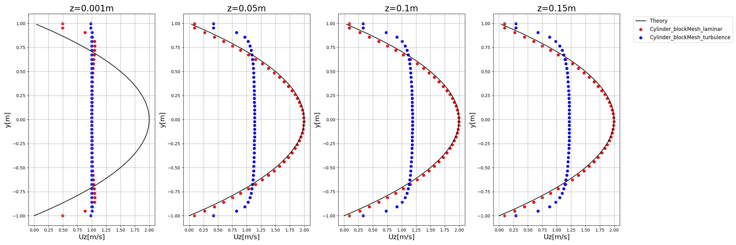
層流と乱流の速度分布の違いを見るために、助走区間の距離を考慮してモデルを作っています。助走区間は層流において十分に発達するまでの距離が長いので、大きくとる必要があります。

乱流状態と同じモデルにするために$Re=4000$での乱流状態での助走区間は$d=20$mmとすると$\frac{L}{d}=10$より、$L=200$mmとなります。
層流において
助走区間の距離$L=200$mmとすると$\frac{L}{d}=0.05Re$よりレイノルズ数$Re=200$なります。念のため助走区間をもっと短くするためにレイノルズ数を小さくして$Re=100$にして解析を行います(この方がより層流側の流れになるため理論値と一致した)。


これによりモデルの円筒の長さは最低200mmにすれば良いことがわかります。
層流の場合の円筒内の流れの近似式はこちらです。
u=2u_{b}\bigg(1-\big(\frac{r}{R}\big)^2\bigg)
\end{align*}
層流の近似式はOpenFOAMでの結果と良い一致を示しています。

フォルダを準備
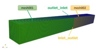
解析を行うにあたって以下のようにmesh001とmesh002という名前のフォルダを準備します。
|
1 2 3 4 5 6 7 8 9 10 11 12 13 14 15 16 17 18 19 20 21 22 23 24 25 26 27 28 29 30 31 32 33 34 35 36 37 38 39 40 41 42 43 44 45 46 47 48 49 50 51 52 53 54 55 56 57 |
. ├── mesh001 │ ├── 0 │ │ ├── U │ │ ├── k │ │ ├── nuTilda │ │ ├── nut │ │ ├── old │ │ │ └── epsilon │ │ ├── omega │ │ └── p │ ├── constant │ │ ├── transportProperties │ │ ├── triSurface │ │ │ ├── model_m.eMesh │ │ │ ├── model_m.obj │ │ │ └── model_m.stl │ │ └── turbulenceProperties │ ├── graph.ipynb │ ├── log.simpleFoam │ └── system │ ├── blockMeshDict │ ├── controlDict │ ├── decomposeParDict │ ├── fvSchemes │ ├── fvSolution │ ├── sampleDict │ ├── solverInfo │ └── streamlines └── mesh002 ├── 0 │ ├── U │ ├── k │ ├── nuTilda │ ├── nut │ ├── old │ │ └── epsilon │ ├── omega │ └── p ├── constant │ ├── transportProperties │ ├── triSurface │ │ ├── model_m.eMesh │ │ ├── model_m.obj │ │ └── model_m.stl │ └── turbulenceProperties ├── graph.ipynb ├── log.simpleFoam └── system ├── blockMeshDict ├── controlDict ├── decomposeParDict ├── fvSchemes ├── fvSolution ├── sampleDict ├── solverInfo └── streamlines |
mesh001(左側)
blockMeshを以下に変えます。
system/blockMeshDict
|
1 2 3 4 5 6 7 8 9 10 11 12 13 14 15 16 17 18 19 20 21 22 23 24 25 26 27 28 29 30 31 32 |
scale 0.001; // Divisions in x/y/z directions. Can be unequal. nx 15; ny 15; nz 100; //modify (省略) Zmin 0.0; Zmax 100; //modify (省略) boundary ( (省略) outlet_inlet { type patch; faces ( (8 9 10 11) (8 12 13 9) (9 13 14 10) (10 14 15 11) (11 15 12 8) ); } ); |
z方向の分割数を100、z方向の長さを100(mm)に変更しています。
blockMeshを実行してメッシュを作成します。
|
1 |
blockMesh |
ParaViewで結果を確認しましょう。


次に、mesh002フォルダに移動してmesh001とは異なるメッシュを作成します。
|
1 |
cd ../mesh002 |
mesh002(右側)
mesh002はmesh001と比べて分割数を大きくするようにします。
system/blockMeshDict
|
1 2 3 4 5 6 7 8 9 10 11 12 13 14 15 16 17 18 19 20 21 22 23 24 25 26 27 28 29 30 31 32 |
scale 0.001; // Divisions in x/y/z directions. Can be unequal. nx 30; //modify ny 30; //modify nz 100; //modify (省略) Zmin 0.0; Zmax 100; //modify (省略) boundary ( (省略) inlet_outlet { type patch; faces ( (0 1 2 3) (0 4 5 1) (1 5 6 2) (2 6 7 3) (7 4 0 3) ); } ); |
こちらのメッシュはmesh001とz=100(mm)でつなぐため、z方向に100mm平行移動する必要があります。
メッシュを移動させるのは「transformPoints 」を使えば良いのですが、使い方がわからないのでhelpで確認します。
|
1 2 3 4 5 6 7 8 9 10 11 12 13 14 15 16 17 18 19 20 21 22 23 24 25 26 27 28 29 30 31 32 33 34 35 36 37 38 39 40 41 42 43 44 45 46 |
transformPoints -help Usage: transformPoints [OPTIONS] Options: -allRegions Use all regions in regionProperties -auto-centre Use bounding box centre as centre for rotations -case <dir> Case directory (instead of current directory) -centre <point> Use specified <point> as centre for rotations -decomposeParDict <file> Alternative decomposePar dictionary file -parallel Run in parallel -recentre Recentre the bounding box before other operations -region <name> Use specified mesh region. Eg, -region gas -regions <wordRes> Use specified mesh region. Eg, -regions gas Or from regionProperties. Eg, -regions '(gas "solid.*")' -rollPitchYaw <vector> Rotate by '(roll pitch yaw)' degrees -rotate <(vectorA vectorB)> Rotate from <vectorA> to <vectorB> - eg, '((1 0 0) (0 0 1))' -rotate-angle <(vector angle)> Rotate <angle> degrees about <vector> - eg, '((1 0 0) 45)' -rotate-x <deg> Rotate (degrees) about x-axis -rotate-y <deg> Rotate (degrees) about y-axis -rotate-z <deg> Rotate (degrees) about z-axis -rotateFields Read and transform vector and tensor fields too -scale <scalar | vector> Scale by the specified amount - Eg, for uniform [mm] to [m] scaling use either '(0.001 0.001 0.001)' or simply '0.001' -time <time> Specify the time to search from and apply the transformation (default is latest) -translate <vector> Translate by specified <vector> before rotations -yawPitchRoll <vector> Rotate by '(yaw pitch roll)' degrees -doc Display documentation in browser -help Display short help and exit -help-compat Display compatibility options and exit -help-full Display full help and exit Transform (translate / rotate / scale) mesh points. Note: roll=rotate about x, pitch=rotate about y, yaw=rotate about z Using: OpenFOAM-2212 (2212) - visit www.openfoam.com Build: _c9081d5d-20230220 (patch=230110) Arch: LSB;label=32;scalar=64 |
z方向に100(mm)移動させるには以下のようにします。
|
1 |
transformPoints -translate '(0 0 0.1)' |
では、ParaViewで確認してみましょう。


mesh001とmesh002を合体(mergeMesh)
では、mesh001とmesh002のメッシュを合体させましょう。
ひとつ上の階層にフォルダ移動して、
|
1 |
cd .. |
フォルダが以下のように見えていることを確認します。
|
1 2 |
ls mesh001 mesh002 |
mesh001をコピーしておきます。
|
1 |
cp -r mesh001 mergeMesh001_002 |
以下のコマンドでメッシュ情報を合体させます。
|
1 |
mergeMeshes -overwrite mergeMesh001_002 mesh002 |
メッシュ情報を合体させただけですので、つなぎ目はつながっていません。
メッシュを結合する(stitchMesh)
では、境界を結合させます。
まずは、先ほどの合体させたメッシュをコピーします。メッシュの結合は「stitchMesh001_002」フォルダで行うことにします。
|
1 |
cp -r mergeMesh001_002 stitchMesh001_002 |
フォルダを移動して、
|
1 |
cd stitchMesh001_002 |
以下の下準備をします。
境界条件ファイルを0/oldに移動させる(0, k, p…の境界の名前がboundaryと一致していないのでエラーになるため)
では、「outlet_inlet」面と「inlet_outlet」面を結合させます。
|
1 |
stitchMesh -overwrite outlet_inlet inlet_outlet |
polyMesh/boundary
|
1 2 3 4 5 6 7 8 9 10 11 12 13 14 15 16 17 18 19 20 21 22 23 24 25 26 27 28 29 30 31 32 33 34 |
5 ( sideWall { type wall; inGroups 1(wall); nFaces 18000; startFace 1677679; } inlet { type patch; nFaces 1125; startFace 1695679; } outlet_inlet { type patch; nFaces 0; startFace 1696804; } inlet_outlet { type patch; nFaces 120; startFace 1696804; } outlet { type patch; nFaces 4500; startFace 1696924; } ) |
「outlet_inlet」の面は0になっていますが、「inlet_outlet」の面の数は120になっています。完全につながると面の数は両方0になるんですが、うまくつながらなかったようです。


間を強引につないでいますね。
例えばわかりやすく「mesh002」のz方向にz=105mm平行移動を以下のようにして境界面を結合させてみます。
|
1 |
transformPoints -translate '(0 0 0.105)' |
outlet_inletが残っていますが、どちらかというとsideWallの一部になっているような感じですね。
モデルの作り方を変える
mesh002のメッシュからやり直します。
mesh002のblockMeshで生成後にz方向への平行移動は1mmとします。
|
1 |
transformPoints -translate '(0 0 0.101)' |

|
1 2 3 4 5 |
cp -r mesh001/constant/polyMesh mergeMesh001_002/constant/ mergeMeshes -overwrite mergeMesh001_002 mesh002 cp -r mergeMesh001_002/constant/polyMesh stitchMesh001_002/constant/ cd stitchMesh001_002 stitchMesh -overwrite outlet_inlet inlet_outlet |
※0フォルダに余計なファイルがある場合はとエラーになるので消してください。
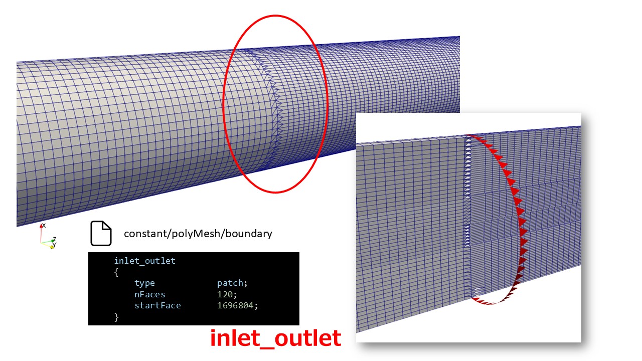

相変わらず「inlet_outlet」面は残りますが壁条件として解析すればいいのではないかと思います。
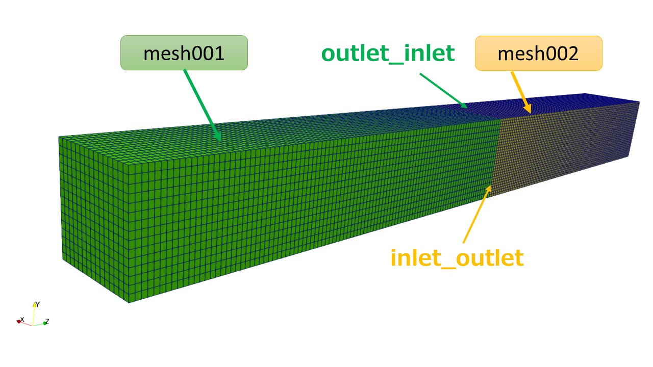
直方体の形状ならどうなるか(結合できるか)
円筒形状だとstitchで結合できないサーフェスができましたが、以下のような直方体ならどうでしょうか。
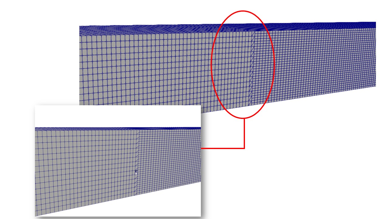

どうやら直方体の場合はうまく面倒が結合しているみたいです。
まとめ
今回は異なるメッシュでの境界面の結合を試みましたが、円筒の場合だと上手く両方の面が消えてくれず残ってしまいました。しかし、直方体の場合は上手く境界の両方の面が消えて結合されました。
円筒の場合のような残った面は側面の面に変わっているようなので、壁条件として解析すれば円筒内流れとしては問題ないのではないかと思います。
気になるようでしたらmergeMeshしたあとに「outlet_inlet」と「inlet_outlet」面は周期境界 (格子の切り方が違う2面をつなぐ Cyclic Arbitrary Mesh Interface (cyclicAMI)タイプ)で設定した方が良いかもしれません。
次回、今回結合させたメッシュで円筒内の流れを解析してみます。
stitchMeshでつながない場合と違いが出るのか確かめます。
おすすめ参考図書
☟こちらは、OpenFOAMの日本語書籍として重宝しているわかりやすい参考書だと思います。
☟こちらもOpenFOMの古いバージョンでの和訳になります。さすがにこちらはバージョンに対する日本語でのケアはしていないので、OpenFOAMに慣れている方は購入しても良いかと思います。僕は「日本語でまとまっている内容」なので少し重宝しています。
☟以下に、もっと初心者向けの同人誌を紹介しておきます。
初心者は「ってか、まずどうやってOpenFOAMをインストールするの?」というところからつまずきがちです。
そんな時は、以下の書籍をおすすめします。
インストール方法とチュートリアルで流体解析を体験・・・ちょっと高度な解析まで解説があります。著者曰くOpenFOAMのバージョンの追跡を行いながら、書籍をアップデートするようなので安心ですね。


