splitMeshRegions :各領域に分割
まずは0.origをコピーして0フォルダを作ります。
|
1 |
cp -r 0.orig |
splitMeshRegionsを行う前に必ず0フォルダを作成する必要があります。
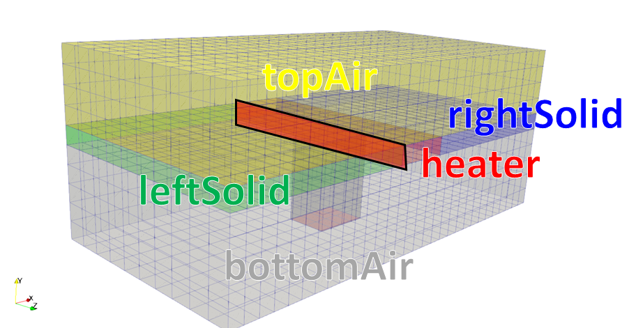
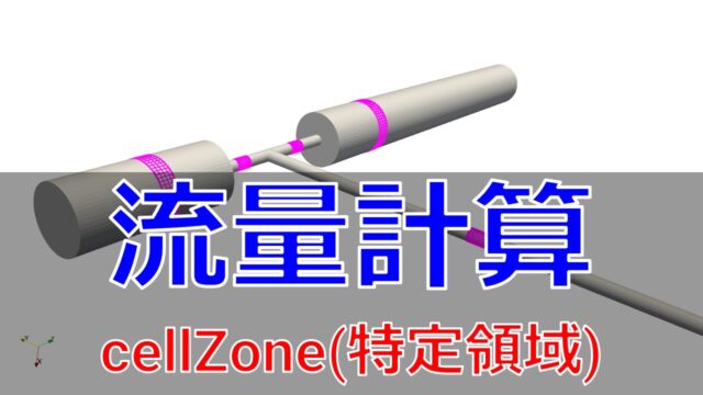
では、splitMeshRegionsを実行してsnappyHexMeshで作成したcellZoneを使って領域の分割を行います。
|
1 |
splitMeshRegions -cellZones -overwrite |
ParaViewで確認。

constant/bottomAir/polyMesh/boundary
|
1 2 3 4 5 6 7 8 9 10 11 12 13 14 15 16 17 18 19 20 21 22 23 24 25 26 27 28 29 30 31 32 33 34 35 36 37 38 39 40 41 42 43 44 45 46 47 48 49 50 51 52 53 54 55 56 57 58 59 60 61 62 63 64 65 66 67 68 69 70 71 72 73 74 |
8 ( minX { type wall; nFaces 80; startFace 11196; } maxX { type wall; nFaces 80; startFace 11276; } minY { type wall; inGroups 1 ( wall ); nFaces 340; startFace 11356; } minZ { type wall; inGroups 1 ( wall ); nFaces 240; startFace 11696; } maxZ { type wall; inGroups 1 ( wall ); nFaces 240; startFace 11936; } bottomAir_to_rightSolid { type mappedWall; inGroups 1 ( wall ); nFaces 520; startFace 12176; sampleMode nearestPatchFace; sampleRegion rightSolid; samplePatch rightSolid_to_bottomAir; } bottomAir_to_leftSolid { type mappedWall; inGroups 1 ( wall ); nFaces 520; startFace 12696; sampleMode nearestPatchFace; sampleRegion leftSolid; samplePatch leftSolid_to_bottomAir; } bottomAir_to_heater { type mappedWall; inGroups 1 ( wall ); nFaces 368; startFace 13216; sampleMode nearestPatchFace; sampleRegion heater; samplePatch heater_to_bottomAir; } ) |
以下のような構造になっています。
|
1 2 3 4 5 6 7 8 9 10 |
regionA_to_regionB { type mappedWall; inGroups 1(wall); nFaces 130; startFace 4550; sampleMode nearestPatchFace; sampleRegion regionA; samplePatch regionB_to_regionA; } |
typeはmappedWallとしておく必要があります。
あとの境界の設定は前回の記事と同じです。
別のページ開くのも面倒だと思いますので以下に書いておきます。
境界条件の設定
Allrun.preを見ると以下のような記述があります。
|
1 2 3 4 5 6 |
# Remove fluid fields from solid regions (important for post-processing) for region in $(foamListRegions solid) do rm -f 0/$region/{nut,alphat,epsilon,k,U,p_rgh} rm -f processor*/0/$region/{nut,alphat,epsilon,k,U,p_rgh} done |
foamListRegionsが「constant/regionProperties」で指定しているリストをします。
|
1 2 3 4 5 |
regions ( fluid (bottomWater topAir) solid (heater leftSolid rightSolid) ); |
foamListRegionsだけだと領域全ての要素をリストにするので、 [bottomWater topAir heater leftSolid rightSolid]というリストになります。
しかし以下のようにregionTypeを指定すると、
|
1 |
foamListRegions [OPTIONS] [regionType ... regionType] |
「foamListRegions solid」とsolidを指定するとsolidだけを要素にするので [heater leftSolid rightSolid]となります。
つまり、上記のdo文は以下のようになります。
|
1 2 3 4 5 6 |
rm -f 0/heater/{nut,alphat,epsilon,k,U,p_rgh} rm -f processor*/0/heater/{nut,alphat,epsilon,k,U,p_rgh} rm -f 0/leftSolid/{nut,alphat,epsilon,k,U,p_rgh} rm -f processor*/0/leftSolid/{nut,alphat,epsilon,k,U,p_rgh} rm -f 0/rightSolid/{nut,alphat,epsilon,k,U,p_rgh} rm -f processor*/0/rightSolid/{nut,alphat,epsilon,k,U,p_rgh} |
既に設定がされていたら設定を消すためものですね。
「rm -f」の「-f」オプションはファイルがあれば削除するというものです。
続いてAllrun.preを見ると以下のようになっています。
|
1 2 3 4 |
for region in $(foamListRegions) do runApplication -s $region changeDictionary -region $region done |
これはsystemフォルダ内で各領域のフォルダ内を用意しその中にchangeDictionaryを用意して境界条件の設定を変更していきます。
system/bottomAir/changeDictionaryDict
|
1 2 3 4 5 6 7 8 9 10 11 12 13 14 15 16 17 18 19 20 21 22 23 24 25 26 27 28 29 30 31 32 33 34 35 36 37 38 39 40 41 42 43 44 45 46 47 48 49 50 51 52 53 54 55 56 57 58 59 60 61 62 63 64 65 66 67 68 69 70 71 72 73 74 75 76 77 78 79 80 81 82 83 84 85 86 87 88 89 90 91 92 93 94 95 96 97 98 99 100 101 102 103 104 105 106 107 108 109 110 111 112 113 114 115 116 117 118 119 120 121 122 123 124 125 126 127 128 129 |
boundary { minX { type wall; } maxX { type wall; } } U { internalField uniform (0.01 0 0); boundaryField { ".*" { type fixedValue; value uniform (0 0 0); } "procBoundary.*" { type processor; } } } T { internalField uniform 300; boundaryField { ".*" { type zeroGradient; } "procBoundary.*" { type processor; } "bottomAir_to_.*" { type compressible::turbulentTemperatureRadCoupledMixed; Tnbr T; kappaMethod fluidThermo; value uniform 300; } } } epsilon { // Set the value on all bc to non-zero. Not used in simulation // since zeroGradient; only used in initialisation. internalField uniform 0.01; boundaryField { ".*" { type epsilonWallFunction; value uniform 0.01; } "procBoundary.*" { type processor; } } } k { internalField uniform 0.1; boundaryField { ".*" { type kqRWallFunction; value uniform 0.1; } "procBoundary.*" { type processor; } } } p_rgh { internalField uniform 1e5; boundaryField { ".*" { type fixedFluxPressure; value uniform 1e5; } "procBoundary.*" { type processor; } } } p { internalField uniform 1e5; boundaryField { ".*" { type calculated; value uniform 1e5; } "procBoundary.*" { type processor; } } } |
上記のスクリプトでchangeDictionaryが実行されると、以下のようにファイルが作成されます。
各領域がどの様に変更されたのかを見ていきます。
0/bottomAir/U
|
1 2 3 4 5 6 7 8 9 10 11 12 13 14 15 16 17 18 19 20 21 22 23 24 25 26 27 28 29 30 31 32 33 34 35 36 37 38 39 40 41 42 43 44 45 46 47 48 49 50 51 |
dimensions [ 0 1 -1 0 0 0 0 ]; internalField uniform ( 0.001 0 0 ); boundaryField { minX { // before changeDictionary // type calculated; // value uniform (0.01 0 0); type fixedValue; value uniform ( 0.001 0 0 ); } maxX { type inletOutlet; value uniform ( 0.01 0 0 ); inletValue uniform ( 0 0 0 ); } minY { type fixedValue; value uniform ( 0 0 0 ); } minZ { type fixedValue; value uniform ( 0 0 0 ); } maxZ { type fixedValue; value uniform ( 0 0 0 ); } bottomWater_to_rightSolid { type fixedValue; value uniform ( 0 0 0 ); } bottomWater_to_leftSolid { type fixedValue; value uniform ( 0 0 0 ); } bottomWater_to_heater { type fixedValue; value uniform ( 0 0 0 ); } } |
0/bottomAir/T
|
1 2 3 4 5 6 7 8 9 10 11 12 13 14 15 16 17 18 19 20 21 22 23 24 25 26 27 28 29 30 31 32 33 34 35 36 37 38 39 40 41 42 43 44 45 46 47 48 49 50 51 52 53 |
dimensions [ 0 0 0 1 0 0 0 ]; internalField uniform 300; boundaryField { minX { type zeroGradient; value uniform 300; } maxX { type zeroGradient; value uniform 300; } minY { type zeroGradient; value uniform 300; } minZ { type zeroGradient; value uniform 300; } maxZ { type zeroGradient; value uniform 300; } bottomAir_to_rightSolid { type compressible::turbulentTemperatureRadCoupledMixed; value uniform 300; Tnbr T; kappaMethod fluidThermo; } bottomAir_to_leftSolid { type compressible::turbulentTemperatureRadCoupledMixed; value uniform 300; Tnbr T; kappaMethod fluidThermo; } bottomAir_to_heater { type compressible::turbulentTemperatureRadCoupledMixed; value uniform 300; Tnbr T; kappaMethod fluidThermo; } } |
|
1 2 3 4 5 6 7 8 9 10 11 12 13 14 15 16 17 18 19 20 21 22 23 24 25 26 27 28 29 30 31 32 33 34 35 36 37 38 39 40 41 42 43 |
dimensions [ 0 0 0 1 0 0 0 ]; internalField uniform 300; boundaryField { minX { type zeroGradient; value uniform 300; } minZ { type zeroGradient; value uniform 300; } maxZ { type zeroGradient; value uniform 300; } leftSolid_to_bottomAir { type compressible::turbulentTemperatureRadCoupledMixed; value uniform 300; Tnbr T; kappaMethod solidThermo; } leftSolid_to_heater { type compressible::turbulentTemperatureRadCoupledMixed; value uniform 300; Tnbr T; kappaMethod solidThermo; } leftSolid_to_topAir { type compressible::turbulentTemperatureRadCoupledMixed; value uniform 300; Tnbr T; kappaMethod solidThermo; } } |
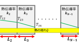
以下のように熱伝導率を持つ厚みにある境界面を挟むことができます。
前回の記事で紹介したチュートリアルは以下のようになっていました。
|
1 2 3 4 5 6 7 8 9 10 11 12 13 14 15 16 17 18 19 20 21 22 23 24 25 26 27 28 29 30 31 32 33 34 35 36 37 38 39 40 41 42 43 44 45 |
dimensions [ 0 0 0 1 0 0 0 ]; internalField uniform 300; boundaryField { minX { type zeroGradient; value uniform 300; } minZ { type zeroGradient; value uniform 300; } maxZ { type zeroGradient; value uniform 300; } leftSolid_to_bottomWater { type compressible::turbulentTemperatureRadCoupledMixed; value uniform 300; Tnbr T; kappaMethod solidThermo; } leftSolid_to_heater { type compressible::turbulentTemperatureRadCoupledMixed; value uniform 300; Tnbr T; kappaMethod solidThermo; thicknessLayers ( 0.001 ); kappaLayers ( 0.0005 ); } leftSolid_to_topAir { type compressible::turbulentTemperatureRadCoupledMixed; value uniform 300; Tnbr T; kappaMethod solidThermo; } } |
- thicknessLayersで厚みを0.001[m]
- kappaLayersで熱伝導率を0.005[W/m K]
この辺の違いも確認しておくと良いですね。
