Case5:特定の境界面の境界層を設定する
patchBoundaryLayersで境界ごとに境界層の厚みも設定できます。
※境界周辺のメッシュサイズを調整して再度メッシュ生成します。
|
1 2 3 4 5 6 7 8 9 10 11 12 13 14 15 16 17 18 19 20 21 22 23 24 25 26 27 28 29 30 31 32 33 34 35 36 37 38 39 40 41 42 43 44 45 46 47 48 49 50 51 52 53 54 55 56 57 58 59 60 61 62 63 64 65 66 67 68 69 70 71 72 73 74 75 76 77 78 79 80 81 82 83 84 85 86 87 88 89 90 91 92 93 94 95 96 97 98 99 100 101 102 103 104 105 106 107 108 109 110 111 112 113 114 115 116 117 118 119 120 121 122 123 124 125 |
surfaceFile "model_m.stl"; // minCellSize 0.001; maxCellSize 0.01; // boundaryCellSize 0.01; localRefinement { "sideWall3" { cellSize 0.004; } "wallOutlet1" { cellSize 0.004; } "outletYmax" { cellSize 0.004; } "outletYmin" { cellSize 0.004; } "sideWall2" { cellSize 0.001; } "wall1" { cellSize 0.004; } "sideWall1" { cellSize 0.004; } "inlet" { cellSize 0.004; } // "orifice0[3-6].*" // { // cellSize 0.3; // } } boundaryLayers { nLayers 3; thicknessRatio 1.2; maxFirstLayerThickness 0.001; patchBoundaryLayers { "sideWall3" { nLayers 3; thicknessRatio 1.2; maxFirstLayerThickness 0.004; allowDiscontinuity 0; } "wallOutlet1" { nLayers 3; thicknessRatio 1.2; maxFirstLayerThickness 0.004; allowDiscontinuity 0; } "outletXmax" { nLayers 3; thicknessRatio 1.2; maxFirstLayerThickness 0.004; allowDiscontinuity 0; } "outletYmax" { nLayers 3; thicknessRatio 1.2; maxFirstLayerThickness 0.004; allowDiscontinuity 0; } "outletYmin" { nLayers 3; thicknessRatio 1.2; maxFirstLayerThickness 0.004; allowDiscontinuity 0; } "sideWall2" { nLayers 3; thicknessRatio 1.2; maxFirstLayerThickness 0.001; allowDiscontinuity 0; } "wall1" { nLayers 3; thicknessRatio 1.2; maxFirstLayerThickness 0.004; allowDiscontinuity 0; } "sideWall1" { nLayers 3; thicknessRatio 1.2; maxFirstLayerThickness 0.004; allowDiscontinuity 0; } "inlet" { nLayers 3; thicknessRatio 1.2; maxFirstLayerThickness 0.004; allowDiscontinuity 0; } // "orifice.*" // { // nLayers 4; // thicknessRatio 1.2; // maxFirstLayerThickness 0.2; // allowDiscontinuity 0; // } } optimiseLayer 1; } |
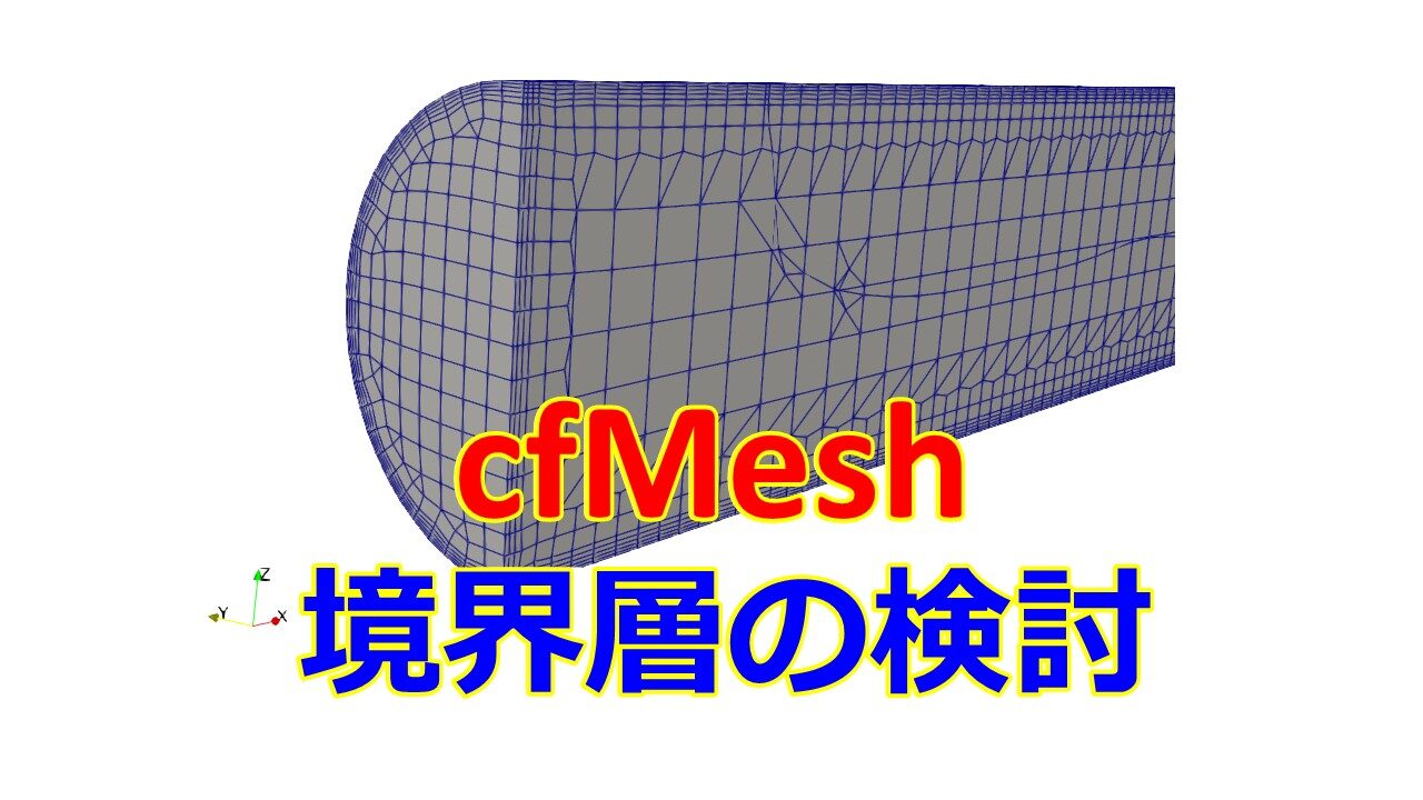
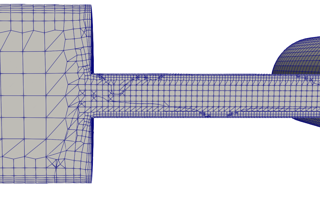
今度は境界層のメッシュサイズも自然になりました。


境界層の層の数も変えることができます。
|
1 2 3 4 5 6 7 8 9 10 11 12 13 14 15 16 17 18 19 20 21 22 23 24 25 26 27 28 29 30 |
surfaceFile "model_m.stl"; // minCellSize 0.001; maxCellSize 0.01; boundaryCellSize 0.01; localRefinement { (省略) } boundaryLayers { nLayers 3; thicknessRatio 1.2; maxFirstLayerThickness 0.001; patchBoundaryLayers { (省略) } "sideWall1" { nLayers 5; thicknessRatio 1.2; maxFirstLayerThickness 0.001; allowDiscontinuity 0; } (省略) } optimiseLayer 1; } |

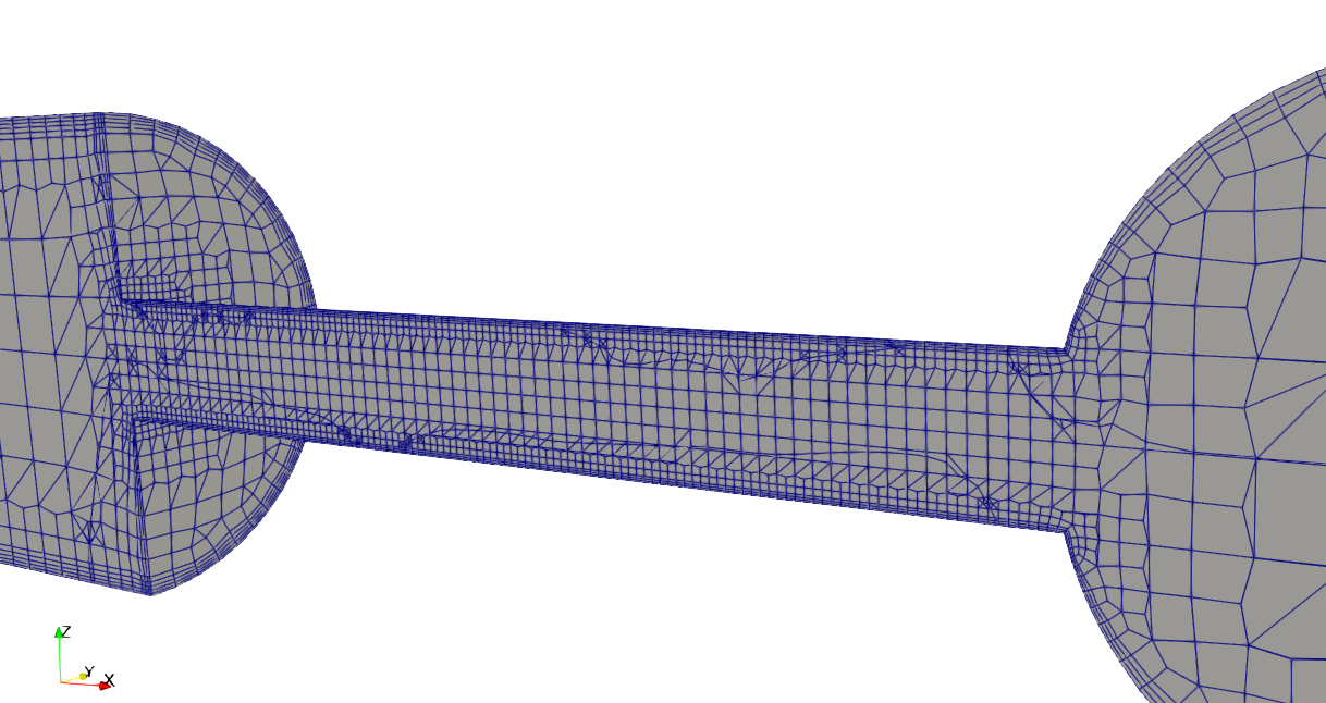
最終的なcfMeshの設定
結局色々試した結果、境界層は3層入れた以下の設定にしました。
|
1 2 3 4 5 6 7 8 9 10 11 12 13 14 15 16 17 18 19 20 21 22 23 24 25 26 27 28 29 30 31 32 33 34 35 36 37 38 39 40 41 42 43 44 45 46 47 48 49 50 51 52 53 54 55 56 57 58 59 60 61 62 63 64 65 66 67 68 69 70 71 72 73 74 75 76 77 78 79 80 81 82 83 84 85 86 87 88 89 90 91 92 93 94 95 96 97 98 99 100 101 102 103 104 105 106 107 108 109 110 111 112 113 114 115 116 117 118 119 120 121 122 123 124 125 126 127 128 129 130 131 132 133 134 135 136 137 138 139 140 141 142 143 144 145 |
/*--------------------------------*- C++ -*----------------------------------*\ | ========= | | | \\ / F ield | cfMesh: A library for mesh generation | | \\ / O peration | | | \\ / A nd | Author: Franjo Juretic | | \\/ M anipulation | E-mail: franjo.juretic@c-fields.com | \*---------------------------------------------------------------------------*/ FoamFile { version 2.0; format ascii; class dictionary; location "system"; object meshDict; } // * * * * * * * * * * * * * * * * * * * * * * * * * * * * * * * * * * * * * // surfaceFile "model_m.stl"; // minCellSize 0.001; maxCellSize 0.01; boundaryCellSize 0.01; localRefinement { "sideWall3" { cellSize 0.004; } "wallOutlet1" { cellSize 0.004; } "outletYmax" { cellSize 0.004; } "outletYmin" { cellSize 0.004; } "sideWall2" { cellSize 0.001; } "wall1" { cellSize 0.004; } "sideWall1" { cellSize 0.004; } "inlet" { cellSize 0.004; } // "orifice0[3-6].*" // { // cellSize 0.3; // } } boundaryLayers { nLayers 3; thicknessRatio 1.0; // maxFirstLayerThickness 0.001; patchBoundaryLayers { "sideWall3" { nLayers 3; thicknessRatio 1.2; maxFirstLayerThickness 0.001; allowDiscontinuity 0; } "wallOutlet1" { nLayers 3; thicknessRatio 1.2; maxFirstLayerThickness 0.001; allowDiscontinuity 0; } "outletXmax" { nLayers 3; thicknessRatio 1.2; maxFirstLayerThickness 0.001; allowDiscontinuity 0; } "outletYmax" { nLayers 3; thicknessRatio 1.2; maxFirstLayerThickness 0.001; allowDiscontinuity 0; } "outletYmin" { nLayers 3; thicknessRatio 1.2; maxFirstLayerThickness 0.001; allowDiscontinuity 0; } "sideWall2" { nLayers 3; thicknessRatio 1.2; maxFirstLayerThickness 0.001; allowDiscontinuity 0; } "wall1" { nLayers 3; thicknessRatio 1.2; maxFirstLayerThickness 0.001; allowDiscontinuity 0; } "sideWall1" { nLayers 3; thicknessRatio 1.2; maxFirstLayerThickness 0.001; allowDiscontinuity 0; } "inlet" { nLayers 3; thicknessRatio 1.2; maxFirstLayerThickness 0.001; allowDiscontinuity 0; } // "orifice.*" // { // nLayers 4; // thicknessRatio 1.2; // maxFirstLayerThickness 0.2; // allowDiscontinuity 0; // } } optimiseLayer 1; } // ************************************************************************* // |


境界層の設定に関してはデフォルト設定の数値を設定してしまうと、特定の面での境界層の設定が効かないことがあるので個別で境界層を設定する方が良いでしょう。
デフォルト設定で一律0.001mの厚みを設定すると、要素数は比較的多い方ではないのに。流体解析した際にものすごく計算時間がかかったりするというのも意識してメッシュを作る必要があります。
|
1 2 3 4 5 6 7 8 9 10 11 12 13 14 15 16 17 18 |
boundaryLayers { // nLayers 3; // thicknessRatio 1.0; // maxFirstLayerThickness 0.001; patchBoundaryLayers { "sideWall3" { nLayers 3; thicknessRatio 1.2; maxFirstLayerThickness 0.001; allowDiscontinuity 0; } (以下省略) } } |
特徴線まわりでメッシュ分割数指定
snappyHexMeshを使用しているときに、特徴線を利用することが多いのですが、cfMeshでも特徴線を利用することができます。
- surfaceFeatureExtructでmodel_m.eMeshを生成
- surfaceFeatureConvert constant/triSurface/model_m.eMesh constant/triSurface/model_m.obj
試してはいませんが、特徴線まわりでメッシュを抽出するには以下のように記述します。
|
1 2 3 4 5 6 7 8 |
edgeMeshRefinement { model_m { edgeFile "model_m.obj"; additionalRefinementLevels 4; } } |
特徴線のmodel_m.objで4分割の再分割を行うという設定です。
ちなみにmodel_m.objはParaViewでも読み込むことができるので、特徴線を確認することができます。
特定領域の再分割
こちらも試していませんが、特定領域の再分割もcfMeshで設定できます。
|
1 2 3 4 5 6 7 8 9 10 11 12 |
objectRefinements { refinement1 { additionalRefinementLevels 2; type box; centre (0 -0.015 0); lengthX 0.1; lengthY 0.015; lengthZ 0.1; } } |
typeは「box, cone, plane」などありますので好みで使い分ければよいかと思います。
境界層のスムーズオプション
こちらのオプションは使ったことがありませんが、「optimiseLayer 1;」とすることで境界層をスムーズにする設定を有効にできます。
|
1 2 3 4 5 6 7 8 9 |
optimiseLayer 1; //境界層スムーズオプション 0:無効 1:有効 optimisationParameters { nSmoothNormals 5; //法線方向スムーズ回数 デフォルト:5 maxNumIterations 5; //最大繰り返し回数 デフォルト:5 featureSizeFactor 0.3; //メッシュサイズと境界層サイズの比 0≦x<1 デフォルト0.3 reCalculateNormals 1; //法線方向計算スイッチ 0or1 0:無効 1:有効 デフォルト1 relThicknessTol 0.1; //隣接する境界層厚さの最大差 0≦x<1 } |
メッシュ品質の確認
ちなみにメッシュ品質は
|
1 |
checkMesh |
により確認ができます。
|
1 2 3 4 5 6 7 8 9 10 11 12 13 14 15 16 17 18 19 20 21 22 23 24 25 26 27 28 29 30 31 32 33 34 35 36 37 38 39 40 41 42 43 44 45 46 47 48 49 50 51 52 53 54 55 56 57 58 59 60 61 62 63 64 65 66 67 68 69 70 71 72 |
Mesh stats points: 170242 faces: 466718 internal faces: 438180 cells: 148341 faces per cell: 6.10012 boundary patches: 9 point zones: 0 face zones: 0 cell zones: 0 Overall number of cells of each type: hexahedra: 140385 prisms: 1200 wedges: 0 pyramids: 812 tet wedges: 0 tetrahedra: 460 polyhedra: 5484 Breakdown of polyhedra by number of faces: faces number of cells 6 1908 7 480 8 96 9 360 12 2576 15 64 Checking topology... Boundary definition OK. Cell to face addressing OK. Point usage OK. Upper triangular ordering OK. Face vertices OK. Number of regions: 1 (OK). Checking patch topology for multiply connected surfaces... Patch Faces Points Surface topology sideWall3 2161 2207 ok (non-closed singly connected) wallOutlet1 5213 5345 ok (non-closed singly connected) outletXmax 400 421 ok (non-closed singly connected) outletYmax 404 417 ok (non-closed singly connected) outletYmin 404 417 ok (non-closed singly connected) sideWall2 7240 7294 ok (non-closed singly connected) wall1 720 784 ok (non-closed singly connected) sideWall1 11592 11648 ok (non-closed singly connected) inlet 404 417 ok (non-closed singly connected) Checking faceZone topology for multiply connected surfaces... No faceZones found. Checking basic cellZone addressing... No cellZones found. Checking geometry... Overall domain bounding box (0 -0.1 -0.020001) (0.7 0.1 0.0200006) Mesh has 3 geometric (non-empty/wedge) directions (1 1 1) Mesh has 3 solution (non-empty) directions (1 1 1) Boundary openness (4.56408e-17 -2.70593e-16 -1.65975e-16) OK. Max cell openness = 4.07934e-16 OK. Max aspect ratio = 11.6722 OK. Minimum face area = 1.47643e-08. Maximum face area = 2.66229e-05. Face area magnitudes OK. Min volume = 2.63257e-12. Max volume = 1.42271e-07. Total volume = 0.000988009. Cell volumes OK. Mesh non-orthogonality Max: 67.368 average: 5.59948 Non-orthogonality check OK. Face pyramids OK. Max skewness = 2.42017 OK. Coupled point location match (average 0) OK. Mesh OK. End |
以下の部分は最低確認するようにしましょう。
- Max aspect ratio:アスペクト比(縦横の比率)→境界層で大きくなりやすいので大きすぎる場合は確認
- non-orthogonality:直交性→70°以上であれば修正
- Max skewness:歪度→4以上だと修正
メッシュ品質の基準は以下のファイルにも記載がありますで確認してみましょう。
|
1 |
$WM_PROJECT_DIR/src/OpenFOAM/meshes/primitiveMesh/primitiveMeshCheck/ |
コマンドでファイルを探す場合は、
|
1 |
find $FOAM_SRC -name "primitiveMeshCheck*" |
以下のように出力されます。
|
1 2 3 4 5 6 7 |
/opt/OpenFOAM/OpenFOAM-v2012/src/OpenFOAM/lnInclude/primitiveMeshCheckEdgeLength.C /opt/OpenFOAM/OpenFOAM-v2012/src/OpenFOAM/lnInclude/primitiveMeshCheckPointNearness.C /opt/OpenFOAM/OpenFOAM-v2012/src/OpenFOAM/lnInclude/primitiveMeshCheck.C /opt/OpenFOAM/OpenFOAM-v2012/src/OpenFOAM/meshes/primitiveMesh/primitiveMeshCheck /opt/OpenFOAM/OpenFOAM-v2012/src/OpenFOAM/meshes/primitiveMesh/primitiveMeshCheck/primitiveMeshCheckEdgeLength.C /opt/OpenFOAM/OpenFOAM-v2012/src/OpenFOAM/meshes/primitiveMesh/primitiveMeshCheck/primitiveMeshCheckPointNearness.C /opt/OpenFOAM/OpenFOAM-v2012/src/OpenFOAM/meshes/primitiveMesh/primitiveMeshCheck/primitiveMeshCheck.C |
primitiveMeshCheck.Cの中身を確認しましょう。
|
1 |
vi $FOAM_SRC/OpenFOAM/meshes/primitiveMesh/primitiveMeshCheck/primitiveMeshCheck.C |
該当箇所は「/primitiveMesh」と打って「n(下へ)」「shift + n(上へ)」で探すことができます。
viを終了するには
ESCボタンを押して「:q」か「:q!」で終了することができます。
|
1 2 3 4 5 |
Foam::scalar Foam::primitiveMesh::closedThreshold_ = 1.0e-6; Foam::scalar Foam::primitiveMesh::aspectThreshold_ = 1000; Foam::scalar Foam::primitiveMesh::nonOrthThreshold_ = 70; // deg Foam::scalar Foam::primitiveMesh::skewThreshold_ = 4; Foam::scalar Foam::primitiveMesh::planarCosAngle_ = 1.0e-6; |
シミュレーションを行う場合、低品質なセルや面によって生じる数値誤差を低減できる数値スキームを選択します。
まとめ
今回はcfMeshで境界層のメッシュ生成についてまとめました。
snappyHexMeshに比べると境界層はcfMeshの方がきれいに作ってくれます。
それにsnappyHexMeshより設定が簡単でメッシュ生成までが速いです。
snappyHexMesh


cfMesh


参考書
FreeCADは以下の書籍で勉強ができます。
OpenFOAMの数少ない日本語の書籍としては以下のものがあります。
バージョンが古いですがOpenFOAMのプログラミング(C++)を学ぶには以下の書籍がわかりやすいです。
